🔌 Top 10 Ultimate Embedded Systems Projects for 2025: From Microcontrollers to Smart Innovation
Why Embedded Systems Projects Matter in 2025: A Deep Dive
Embedded systems are the silent backbone of modern tech—powering everything from smartwatches to industrial robots. In 2025, demand is booming for engineers who can design efficient, low-level systems that interact with the physical world. Whether you're building for IoT, automotive, aerospace, or consumer electronics, embedded projects are your ticket to a future-proof skill set.
If you're aiming to crack core jobs, dominate embedded interviews, or stand out in the sea of resumes, these 10 cutting-edge projects will give your portfolio the power it needs.
The Unseen Powerhouse: Why Embedded Systems are More Critical Than Ever
In 2025, the pervasive nature of technology means embedded systems are no longer just components; they are the intelligent core of countless innovations. Their importance is driven by several converging trends:
1. Explosive Growth of IoT (Internet of Things): From smart homes and connected cities to industrial IoT (IIoT) and smart agriculture, virtually every "thing" that connects to the internet relies on an embedded system. These devices need to be low-power, efficient, secure, and capable of real-time processing, all of which fall squarely within the domain of embedded systems engineering. Project experience in IoT, especially with edge computing and sensor integration, is highly sought after.
2. The Rise of AI at the Edge: As AI moves beyond the cloud, embedded systems are becoming crucial platforms for deploying machine learning models directly on devices. This "AI at the edge" enables faster decision-making, reduced latency, enhanced privacy, and lower bandwidth consumption. Projects demonstrating AI/ML integration on microcontrollers or embedded Linux platforms are incredibly valuable.
3. Automotive and Autonomous Vehicles: The automotive industry is undergoing a massive transformation, with embedded systems at its heart. Modern vehicles contain hundreds of embedded control units (ECUs) managing everything from engine performance and infotainment to advanced driver-assistance systems (ADAS) and fully autonomous driving. Expertise in automotive-grade embedded systems, functional safety (ISO 26262), and real-time operating systems (RTOS) is paramount.
4. Industrial Automation and Robotics (Industry 4.0): The push towards Industry 4.0 demands intelligent, interconnected machinery. Embedded systems are the brains behind industrial robots, automated assembly lines, predictive maintenance sensors, and sophisticated control systems. Projects involving industrial communication protocols (e.g., Modbus, EtherCAT), motor control, and sensor fusion are highly relevant.
5. Miniaturization and Power Efficiency: Consumer demand for smaller, more powerful, and longer-lasting devices (wearables, smartphones, medical implants) constantly pushes the boundaries of embedded system design. Engineers proficient in ultra-low-power design, battery management, and optimizing code for constrained environments are in high demand.
6. Security and Reliability: With more devices connected and controlling critical functions, the security and reliability of embedded systems are non-negotiable. Designing systems resistant to cyber threats, ensuring data integrity, and implementing robust error handling are vital skills that embedded projects can showcase.
The Unrivaled Benefits of Embedded Systems Projects for Your Career
Engaging in embedded systems projects in 2025 offers concrete advantages for aspiring and experienced engineers alike:
- Mastery of Core Engineering Principles: Embedded projects force you to grapple with fundamental concepts like microcontroller architectures, digital logic, analog circuits, data structures, algorithms, and real-time constraints. This deep technical understanding is invaluable for any engineering discipline.
- Hands-on Hardware-Software Integration: Unlike purely software or hardware roles, embedded systems demand a holistic understanding of how code interacts with physical components. This practical experience is highly valued by employers.
- Problem-Solving Prowess: Debugging embedded systems often requires creative problem-solving, combining knowledge of electronics, programming, and system-level thinking. This hones critical analytical skills.
- Showcasing Practical Skills over Theory: While academic knowledge is important, practical projects demonstrate your ability to apply theory to real-world challenges, making you a more attractive candidate.
- Building a Tangible Portfolio: A well-documented embedded project provides a concrete example of your skills and dedication, setting you apart from candidates with only theoretical knowledge or generic software projects.
- Gateway to Niche and High-Demand Fields: Embedded systems skills open doors to specialized and well-paying sectors like automotive, aerospace, medical devices, defense, and industrial automation.
- Future-Proofing Your Skill Set: As technology continues to evolve, the fundamental principles of embedded systems design remain constant. The ability to work at the hardware-software interface will always be in demand, regardless of specific technologies.
- Cracking Core Jobs and Dominating Interviews: Companies hiring for embedded roles are keenly interested in candidates who have tinkered with microcontrollers, written low-level drivers, or debugged hardware issues. Projects provide perfect talking points and demonstrate genuine interest and capability.
By focusing on cutting-edge embedded projects in 2025, you're not just building devices; you're building a robust, future-proof career path in one of the most critical and exciting fields of modern technology.
Table of Content:
1. Smart Health Monitoring Wearable
2. Gesture-Controlled Smart Home System
3. ESP32-Based Weather Station with Web Dashboard
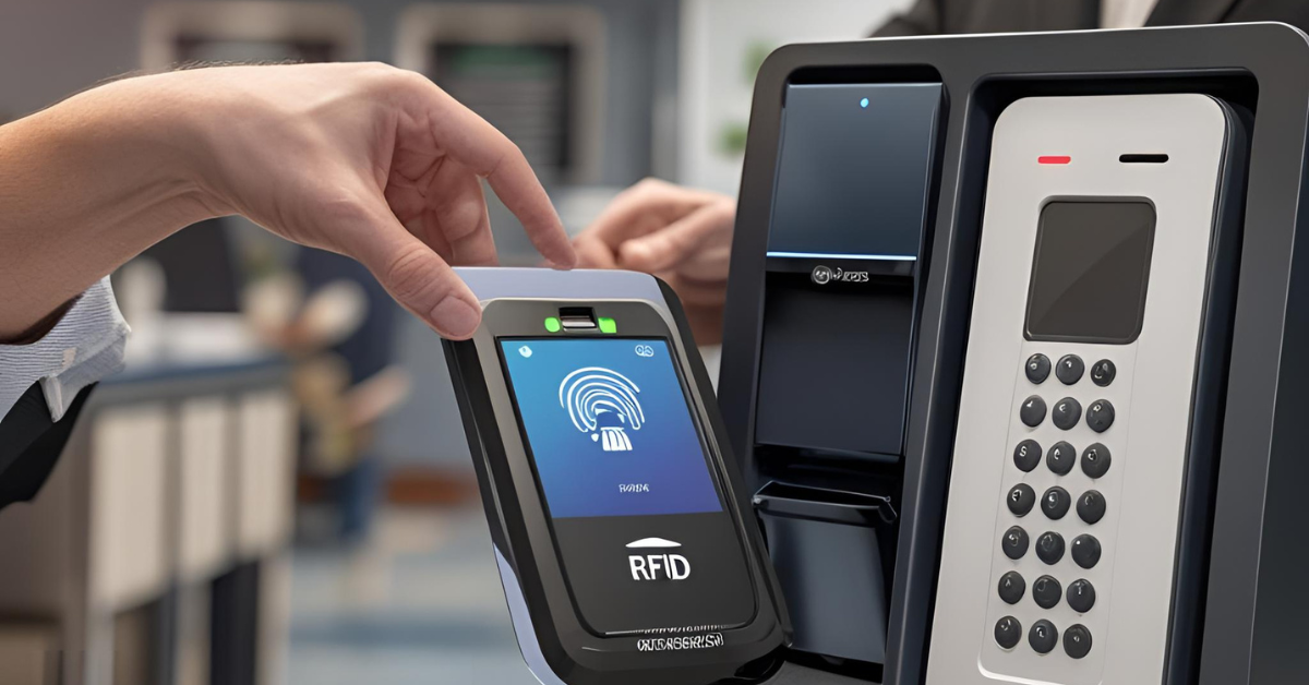
4. Smart Attendance System with RFID + Cloud Sync
5. Automated Plant Irrigation System
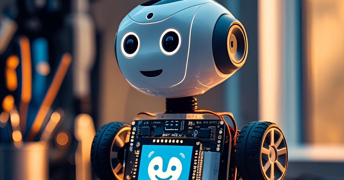
6. Voice-Controlled Robot Using Arduino & Bluetooth
7. Real-Time Object Avoiding Car (Ultrasonic + L298N)
8. Home Security System with GSM & PIR Sensors
9. Industrial Machine Monitoring Unit (Vibration + MQTT)
10. AI-Powered Face Detection System with Raspberry Pi + OpenCV
1. Smart Health Monitoring Wearable
🧠 Tech Stack:
- Microcontroller: Arduino Nano (or ESP32 for advanced features/Wi-Fi)
- Sensors:
- Pulse Sensor (e.g., KY-039 or MAX30102 for heart rate and SpO2)
- Temperature Sensor (e.g., DS18B20 or LM35, optional but recommended for comprehensive monitoring)
- Display: OLED Display (e.g., 0.96" I2C OLED)
- Communication: BLE Module (e.g., HC-05 for basic serial, HM-10 for full BLE, or ESP32's built-in BLE)
- Power: Small LiPo Battery with charging module (e.g., TP4056)
- Enclosure: 3D-printed wristband or compact casing
📦 Project Overview & Concept:
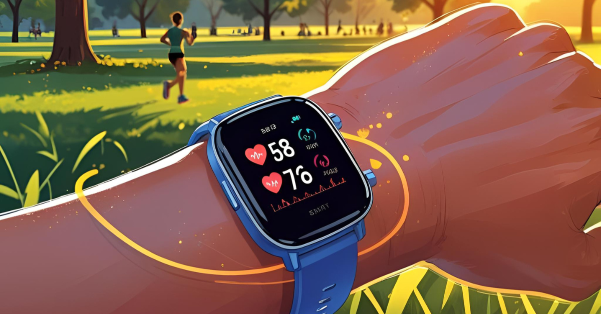
The Smart Health Monitoring Wearable is a miniature, non-invasive device designed to continuously or periodically track essential physiological parameters of the user. The core concept revolves around empowering individuals with real-time insights into their health, enabling proactive health management and providing peace of mind.
The device will be worn on the wrist, finger, or another suitable body part. It will leverage a combination of sensors to acquire vital data. For instance, a pulse sensor will detect heart rate and, if using an advanced sensor like the MAX30102, also measure blood oxygen saturation (SpO2). An optional temperature sensor can provide body temperature readings.
The collected data will be processed by the Arduino Nano (or ESP32), displayed instantly on a compact OLED screen for immediate feedback to the user, and simultaneously transmitted wirelessly via a Bluetooth Low Energy (BLE) module to a connected smartphone application. The mobile app, developed separately, will serve as a dashboard for visualizing trends, logging historical data, setting up custom alerts for abnormal readings, and potentially sharing data with healthcare providers (with user consent).
This project requires careful consideration of power efficiency, sensor accuracy, compact design, and robust wireless communication, making it an excellent demonstration of embedded systems design for wearable technology.
📈 Why Build It: Benefits & Impact
Building a Smart Health Monitoring Wearable in 2025 is highly relevant and offers numerous benefits, both personally and professionally:
- Rising Health Awareness & Remote Monitoring: The global focus on personal health and preventive care has surged. There's a growing demand for devices that enable individuals to monitor their health from home, reducing the need for frequent clinic visits, especially for chronic condition management.
- Market Demand for Wearables: The wearable technology market continues its explosive growth. Gaining experience in this sector positions you at the forefront of consumer electronics and health tech innovation.
- Proactive Health Management: This device facilitates early detection of potential health issues, allowing users to take timely action or seek medical advice, potentially preventing serious conditions.
- Peace of Mind for Users and Caregivers: For individuals with specific health concerns or for families monitoring elderly relatives, the ability to receive real-time alerts for critical vital signs offers significant reassurance.
- Skill Enhancement for Embedded Engineers: This project is a comprehensive learning experience, covering:
- Sensor Interfacing: Working with analog and digital sensors (Pulse, SpO2, Temperature).
- Microcontroller Programming: Efficient data acquisition, processing, and display.
- Low-Power Design: Essential for battery-powered wearables.
- Wireless Communication (BLE): Understanding protocols for data transmission to mobile devices.
- Basic UI/UX: Designing an intuitive display for the wearable.
- Mobile App Integration: (If you extend to building the app) Experience in full-stack IoT development.
- Enclosure Design: Practical experience in mechanical design and manufacturing (e.g., 3D printing).
- Portfolio Differentiator: A functional, well-documented smart health wearable is a powerful project for your resume, showcasing expertise in IoT, health tech, and embedded systems, which are highly sought after by employers in various industries (medical devices, consumer electronics, sports tech).
🏥 Use Cases:
This Smart Health Monitoring Wearable has a wide array of practical applications:
- Personal Fitness & Wellness:
- Fitness Tracking: Monitoring heart rate during exercise, helping users stay within target heart rate zones for optimal workouts.
- Stress Monitoring: Tracking resting heart rate variability as an indicator of stress levels.
- Sleep Tracking: (With advanced algorithms) Monitoring heart rate patterns during sleep to infer sleep stages.
- Elderly Care & Remote Monitoring:
- Fall Detection (with additional accelerometer): Sending alerts to caregivers if a fall is detected.
- Vitals Tracking for Seniors: Remotely monitoring heart rate and SpO2 for elderly individuals, providing reassurance to family members or caregivers.
- Medication Reminders: (Integrated with the mobile app) Sending notifications to the wearable.
- Chronic Disease Management:
- Cardiac Patients: Regular monitoring of heart rate and rhythm for individuals with heart conditions.
- Respiratory Conditions: SpO2 monitoring for patients with asthma, COPD, or other respiratory illnesses.
- Post-Operative Monitoring: Basic vital sign tracking during recovery at home.
- Workplace Safety:
- Monitoring vital signs of workers in hazardous environments (e.g., high-temperature areas, confined spaces) to detect signs of fatigue or distress.
- Sports & Athletics:
- Monitoring athletes' physiological responses during training to optimize performance and prevent overexertion.
- Educational & Hobbyist Tool:
- An excellent platform for learning about sensor integration, embedded programming, and wireless communication.
This project is a perfect blend of hardware, software, and real-world utility, making it an incredibly valuable addition to any embedded systems portfolio.
Project 1: Smart Health Monitoring Wearable Codes:
🔗 View Project Code on GitHubHow to Use and Set Up:
1. Arduino IDE Setup:
- Download and install the Arduino IDE if you haven't already.
- Go to
Tools > Board > Arduino AVR Boardsand selectArduino Nano. - Go to
Tools > Portand select the serial port connected to your Arduino Nano.
2. Install Libraries:
- Open the Arduino IDE.
- Go to
Sketch > Include Library > Manage Libraries.... - Search for and install the following libraries:
Adafruit GFX LibraryAdafruit SSD1306Adafruit MAX30105OneWireDallasTemperature
- The
SoftwareSeriallibrary is typically built into the Arduino IDE, so no extra installation is needed for that.
3. Wiring:
- Follow the detailed wiring guide provided in the comments within the code. Pay special attention to the DS18B20's 4.7K Ohm pull-up resistor and the potential need for a voltage divider for the HC-05's RX pin if your HC-05 is 3.3V and your Arduino is 5V (most HC-05 modules have onboard regulators, but it's good to check).
4. Upload the Code:
- Copy the entire code block into your Arduino IDE.
- Click the "Verify" button (checkmark icon) to compile the code.
- Click the "Upload" button (right arrow icon) to upload the code to your Arduino Nano.
5. Monitor Output:
- Open the Serial Monitor (
Tools > Serial Monitor) with the baud rate set to9600to see debugging information and sensor readings.
6. Bluetooth Connection:
- Once the Arduino is running, the HC-05/HM-10 module should become discoverable by your smartphone.
- Pair your phone with the Bluetooth module. The default PIN for HC-05 is usually
1234or0000. - Use a generic Bluetooth serial terminal app on your smartphone (search "Bluetooth Serial Terminal" on Play Store/App Store). Connect to the HC-05/HM-10 module. You should start receiving the formatted sensor data (e.g.,
HR:75,SpO2:98.5,TempC:36.7\n).
Next Steps and Improvements:
- Accurate SpO2 Calculation: The
Adafruit_MAX30105library provides raw IR/Red data and a basic SpO2 function. For medical-grade accuracy, implementing a more sophisticated SpO2 algorithm (based on Maxim Integrated's application notes or more advanced libraries like SparkFun's MAX30102 library) would be necessary. - Mobile Application Development: Develop a dedicated Android/iOS app to connect to the BLE module, parse the incoming data, display it beautifully (e.g., using charts), log historical data, and set up custom alerts.
- Power Optimization: For a true wearable, implement deeper sleep modes for the Arduino Nano (if using just Nano) or utilize the ESP32's advanced power management features (Light Sleep, Deep Sleep) if you switch to it.
- Data Storage: Implement local data storage on an SD card module if you want to log data without continuous Bluetooth connection.
- Enclosure Design: Refine your 3D-printed enclosure for comfort, durability, and sensor placement for optimal readings.
- Error Handling: Add more robust error handling for sensor failures, Bluetooth connection drops, and invalid readings.
- Calibration: Calibrate your temperature and pulse oximetry readings against known accurate devices.
2. Gesture-Controlled Smart Home System
🧠 Tech Stack:
- Microcontrollers:
- Transmitter Unit: Arduino Uno (or a smaller Pro Mini/Nano for wearable comfort)
- Receiver Unit: Arduino Uno (or NodeMCU/ESP32 for Wi-Fi capabilities if extending)
- Sensors:
- Accelerometer: ADXL345 (3-axis accelerometer for detecting motion and orientation)
- Wireless Communication:
- RF Transmitter/Receiver Module: 433 MHz RF modules (e.g., FS1000A/XY-MK-5V pair for basic on/off, or NRF24L01 for more robust two-way communication). For higher reliability and range, NRF24L01 is highly recommended.
- Actuators/Controlled Devices:
- Relay Module: 1, 2, 4, or 8-channel relay board (to switch AC loads like lights, fans).
- Appliances: Standard household appliances (lights, fans, lamps, small ACs - connect via relays).
- Optional Enhancements:
- Display: Small OLED or LCD for status feedback on the transmitter or receiver.
- Power: 9V battery for the transmitter unit, USB/external power supply for the receiver.
- Enclosures: 3D-printed cases for both the wearable gesture unit and the receiver box.
📦 Project Overview & Concept:
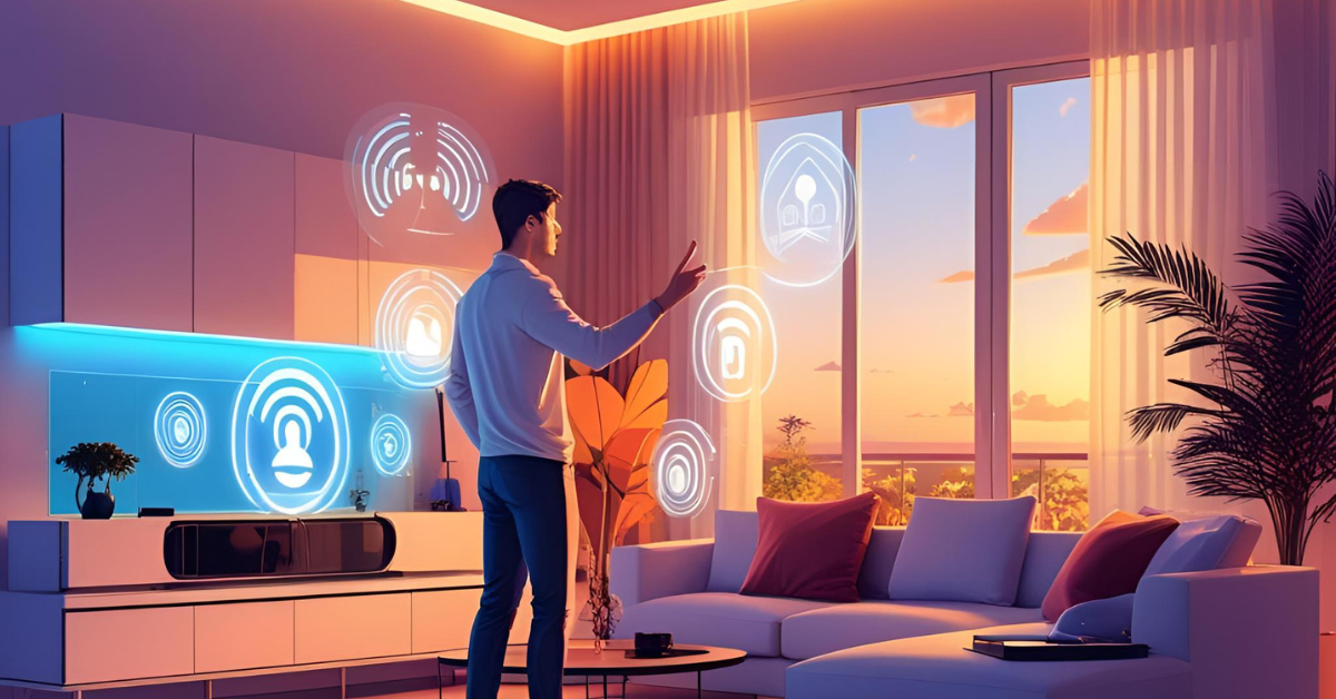
The Gesture-Controlled Smart Home System aims to provide an intuitive and futuristic way to interact with home appliances using simple hand gestures. Imagine a user wearing a small device on their hand or wrist; a flick of the wrist turns on the lights, a hand wave adjusts the fan speed, or a specific motion changes the TV channel.
The system comprises two main parts:
1. The Transmitter Unit (Gesture Module): This is the wearable component, typically built around an Arduino Uno (or smaller form factor) and an ADXL345 accelerometer. The accelerometer continuously reads the motion and orientation of the user's hand. Specific patterns of movement (e.g., an upward flick, a left-to-right swipe, a circular motion) are programmed and mapped to distinct commands. Once a gesture is recognized, the Arduino encodes this command and transmits it wirelessly via the RF transmitter module.
2. The Receiver Unit (Home Control Module): This unit, also typically an Arduino Uno, is connected to the RF receiver module and a relay board. It constantly listens for incoming wireless commands. Upon receiving a command, the Arduino decodes it and, based on the pre-programmed mapping, activates or deactivates the corresponding relay. Each relay is connected to a specific home appliance (e.g., a light bulb, a fan, a socket for a TV).
This project delves into motion sensing, pattern recognition (even simple ones), wireless data transmission, and electrical switching, offering a comprehensive dive into embedded control for home automation.
📈 Why Build It: Benefits & Impact
Building a Gesture-Controlled Smart Home System in 2025 offers compelling advantages:
- Exploration of Human-Computer Interaction (HCI): This project moves beyond traditional buttons and switches, exploring a more natural and expressive form of control. It's an excellent way to experiment with intuitive user interfaces.
- Intersection of UX, Embedded Control, and Wireless Protocols: It perfectly demonstrates how these three critical areas converge:
- User Experience (UX): Designing gestures that are natural, memorable, and efficient.
- Embedded Control: Programming microcontrollers to interpret sensor data and control external hardware.
- Wireless Protocols: Understanding how data is transmitted and received reliably over the air.
- Future of Smart Homes: While voice control is prevalent, gesture control offers an alternative, silent, and often quicker interaction method, especially in environments where voice commands might be impractical or undesirable.
- Skill Development in Key Areas:
- Sensor Data Processing: Reading and interpreting raw accelerometer data, filtering noise, and detecting specific motion patterns.
- Wireless Communication: Implementing robust data encoding and decoding for reliable RF transmission.
- Relay Control: Safely interfacing microcontrollers with AC mains power through relays.
- Algorithm Design: Developing algorithms for gesture recognition.
- System Integration: Bringing together multiple hardware components and software modules to form a cohesive system.
- Portfolio Standout: A gesture-controlled system is visually impressive and demonstrates innovative thinking, making your portfolio memorable to potential employers in IoT, home automation, and human-interface design roles.
- Accessibility Potential: Gesture control can offer an alternative interface for individuals with mobility challenges, contributing to assistive technology solutions.
🏡 Use Cases:
The applications of a Gesture-Controlled Smart Home System extend beyond simple on/off control:
- Home Automation & Convenience:
- Lighting Control: Turning lights on/off, dimming, or changing colors with specific hand movements.
- Fan Speed Control: Gesturing up or down to increase or decrease fan speed.
- Appliance Activation: Turning on/off power to coffee makers, stereos, or other plug-in devices via smart plugs connected to relays.
- Curtain/Blind Control: Opening or closing motorized blinds with a simple gesture.
- Entertainment Systems:
- TV/Media Player Control: Changing channels, adjusting volume, pausing/playing media.
- Gaming: Potentially used as a custom controller for simple interactive games.
- Accessibility Solutions:
- Assisted Living: Providing an alternative control method for individuals with limited mobility who might struggle with small buttons or voice commands.
- Industrial & Robotics Control (Advanced Concept):
- Remote Robot Manipulation: Imagine controlling a robotic arm's movement with hand gestures (requires much higher precision and feedback, but the foundation is similar).
- Warehouse Automation: Triggering specific actions in automated systems with predefined gestures.
- Interactive Displays/Presentations:
- Controlling slides, zooming in/out, or interacting with digital content using hand gestures in a presentation setting.
This project is not just about making things smart; it's about making them interact with us in a more intuitive, natural, and engaging way.
Project 2: Gesture-Controlled Smart Home System Codes:
🔗 View Project Code on GitHub
How to Use and Set Up:
This project requires two separate Arduino boards. You will upload the Transmitter Unit code to one Arduino (e.g., Arduino Nano for the wearable part) and the Receiver Unit code to another Arduino (e.g., Arduino Uno for the home control part).
1. Arduino IDE Setup:
- Download and install the Arduino IDE.
- Go to
Tools > Board > Arduino AVR Boardsand selectArduino Uno(for the receiver) andArduino Nano(for the transmitter, if applicable). - Select the correct
Tools > Portfor each board when uploading.
2. Install Libraries:
- Open the Arduino IDE.
- Go to
Sketch > Include Library > Manage Libraries.... - Search for and install:
RF24by TMRh20Adafruit Unified Sensor(for Transmitter)Adafruit ADXL345(for Transmitter)
- The
SPIandWirelibraries are built-in.
3. Wiring Guide:
Transmitter Unit (Arduino Nano / Uno):
- NRF24L01:
- VCC to 3.3V (important! Use 3.3V, not 5V directly for the module, although dev boards often have regulators)
- GND to GND
- CE to Digital Pin 9
- CSN to Digital Pin 10
- SCK to Digital Pin 13 (SPI Clock)
- MOSI to Digital Pin 11 (SPI Data Out)
- MISO to Digital Pin 12 (SPI Data In)
- ADXL345 (I2C):
- VCC to 5V (or 3.3V if your module supports it)
- GND to GND
- SDA to Analog Pin A4
- SCL to Analog Pin A5
Receiver Unit (Arduino Uno):
- NRF24L01:
- VCC to 3.3V (important!)
- GND to GND
- CE to Digital Pin 9
- CSN to Digital Pin 10
- SCK to Digital Pin 13
- MOSI to Digital Pin 11
- MISO to Digital Pin 12
- Relay Module (e.g., 4-channel relay):
- VCC to 5V (for relay power, can be Arduino's 5V or external)
- GND to GND
- IN1 to Digital Pin 2 (LIGHT_RELAY_PIN)
- IN2 to Digital Pin 3 (FAN_RELAY_PIN)
- IN3 to Digital Pin 4 (AC_RELAY_PIN)
- Connect the NO (Normally Open) and Common terminals of the relays to your AC appliances. Exercise extreme caution when working with AC mains voltage. If unsure, consult a qualified electrician.
4. Upload the Code:
- For Transmitter:
- In the provided code, uncomment the
// Uncomment this block for the TRANSMITTER UNITsection and comment out theReceiver Unitsection. - Upload this code to your Transmitter Arduino.
- In the provided code, uncomment the
- For Receiver:
- In the provided code, uncomment the
// Uncomment this block for the RECEIVER UNITsection and comment out theTransmitter Unitsection. - Upload this code to your Receiver Arduino.
- In the provided code, uncomment the
5. Testing:
- Open the Serial Monitor for both Arduinos (one at a time, or use two instances of the IDE/serial monitor programs if your OS allows).
- Observe the "Transmitter" output when you perform gestures.
- Observe the "Receiver" output and how the relays click in response to the gestures.
Next Steps and Improvements:
- Gesture Recognition Refinement: The current gesture detection is basic (based on peak acceleration in X or Y). You could implement:
- Machine Learning: Train a small ML model (e.g., using TinyML/TensorFlow Lite Micro) on different gesture patterns for more robust and complex gesture recognition.
- State Machine: A more sophisticated state machine to track sequences of movements for complex gestures.
- Dynamic Thresholds: Adjust thresholds based on environmental noise or user calibration.
- Two-Way Communication: Implement a system where the receiver sends an acknowledgment back to the transmitter to confirm command reception.
- User Feedback: Add LEDs or a small buzzer to the transmitter unit to give feedback on gesture recognition and successful command transmission.
- Power Optimization: For the wearable transmitter, optimize power consumption by putting the Arduino and NRF24L01 into sleep modes between gesture checks.
- Mobile App Control: Instead of fixed gestures, you could build a mobile app that allows users to train custom gestures and associate them with commands, making the system more versatile.
- More Appliances: Expand the number of relays and commands to control more appliances.
- Safety Features: Implement emergency stop mechanisms or fail-safes for the home appliances.
- Enclosure: Design and 3D-print a comfortable, ergonomic enclosure for the wearable transmitter unit and a secure box for the receiver unit.

🚀 Ready to turn your passion for hardware into real-world innovation?
At Huebits, we don’t just teach Embedded Systems — we train you to build smart, connected, real-time solutions using the tech stacks that power today’s most advanced devices.
From microcontrollers to IoT deployments, you’ll gain hands-on experience building end-to-end systems that sense, compute, and communicate — built to thrive in the field, not just on paper.
🧠 Whether you're a student, aspiring embedded engineer, or future IoT architect, our Industry-Ready Embedded Systems & IoT Engineering Program is your launchpad.
Master C, Embedded C++, MicroPython, FreeRTOS, ESP32, STM32, and cloud integration with AWS IoT — all while working on real-world projects that demand precision, problem-solving, and execution.
🎓 Next Cohort Starts Soon!
🔗 Join Now and secure your place in the IoT revolution powering tomorrow’s ₹1 trillion+ connected economy.
3. ESP32-Based Weather Station with Web Dashboard
🧠 Tech Stack:
- Microcontroller: ESP32 (e.g., ESP32-WROOM-32 DevKitC) - Chosen for its integrated Wi-Fi and Bluetooth, dual-core processor, and ample GPIO pins.
- Sensors:
- DHT22: For accurate ambient temperature and humidity readings. (Alternative: BME280 for combined Temp/Humidity/Pressure, or DHT11 for basic, less accurate readings).
- BMP180 (or BMP280/BME280): For atmospheric pressure and additional temperature readings (BME280 is a strong upgrade as it combines all three parameters in one sensor).
- Optional Sensors:
- Light Sensor (LDR or BH1750): To measure ambient light intensity.
- Rain Sensor: To detect rainfall.
- UV Sensor: To measure UV index.
- Wind Speed/Direction Sensor: For advanced weather monitoring.
- Frontend/Web Technologies:
- HTML5: For structuring the web page.
- CSS3: For styling and layout of the dashboard.
- JavaScript: For dynamic content updates, data visualization (e.g., charts using libraries like Chart.js or D3.js), and asynchronous data fetching.
- Backend/Communication:
- ESP32 Web Server (AsyncWebServer library): To serve the web pages and handle API requests for sensor data.
- MQTT (Optional but Recommended): For robust, lightweight, and efficient data communication to a broker, enabling remote access and integration with other IoT platforms.
- Wi-Fi Connectivity: Built-in to the ESP32.
📦 Project Overview & Concept:
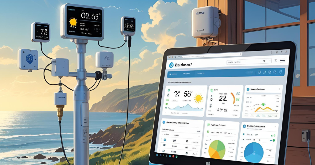
The ESP32-Based Weather Station with Web Dashboard is a comprehensive IoT project that integrates hardware for data acquisition with software for data visualization and remote access. The core concept is to create a localized weather monitoring system that can be accessed from any web browser on the same network (or remotely, if configured).
The system consists of:
- Hardware Module: An ESP32 microcontroller board connected to various environmental sensors (DHT22 for temperature/humidity, BMP180 for pressure). This module will be housed in a protective, weather-resistant enclosure if deployed outdoors.
- Embedded Firmware: The ESP32 will run custom firmware written in Arduino IDE (C++). This firmware will:
- Initialize and read data from the connected sensors at regular intervals.
- Establish and maintain a Wi-Fi connection to the local network.
- Host a basic web server. When a client (web browser) connects, it serves the HTML, CSS, and JavaScript files for the dashboard.
- Implement an API endpoint (e.g.,
/data) that, when requested by the JavaScript in the web page, sends the latest sensor readings in a structured format (e.g., JSON). - (Optional but Recommended) Publish sensor data to an MQTT broker, allowing the data to be easily consumed by other applications or cloud platforms.
- Web Dashboard: This is the user interface, developed using standard web technologies (HTML, CSS, JavaScript). It will be served directly from the ESP32's internal file system (or SPIFFS). The JavaScript code will periodically fetch updated sensor data from the ESP32's web server API and dynamically update the dashboard. This dashboard can display:
- Current temperature, humidity, and pressure readings.
- Historical graphs of these parameters over time.
- Status indicators (e.g., Wi-Fi connectivity).
This project brilliantly showcases the ESP32's capabilities as a powerful IoT device, demonstrating local data acquisition, network communication, and web hosting in a single, compact package.
📈 Why Build It: Benefits & Impact
Building an ESP32-Based Weather Station with Web Dashboard in 2025 offers a wealth of benefits for your skill set and portfolio:
- Seamless Integration of Embedded Systems, IoT, and Frontend: This project is a perfect example of a full-stack IoT application. You'll gain hands-on experience across hardware interfacing, embedded programming, network communication, and web development.
- Mastering the ESP32: You'll become proficient with the ESP32's Wi-Fi capabilities, web server functionalities, and sensor integration, which are fundamental skills for countless IoT applications.
- Real-Time Data Handling: Learning to collect, process, and present real-time sensor data is crucial for many industrial, environmental, and consumer IoT projects.
- Practical Web Development Experience: You'll apply HTML, CSS, and JavaScript in a practical context, understanding how web technologies interact with embedded devices. Experience with fetching and parsing JSON data from an API is also valuable.
- Understanding Networking Protocols: You'll delve into HTTP for web serving and potentially MQTT for lightweight messaging, essential for scalable IoT solutions.
- Low-Cost, High-Impact Project: The components are relatively inexpensive, but the project's scope and the skills it teaches are significant, making it an excellent return on investment for your learning.
- Portfolio Powerhouse: This project clearly demonstrates your ability to build a complete IoT solution from sensor to dashboard, highly attractive to employers in smart home, environmental monitoring, agriculture tech, and general IoT development roles.
- Scalability Potential: The foundation laid by this project can easily be extended to larger sensor networks or integrated with cloud platforms (e.g., AWS IoT, Google Cloud IoT, Adafruit IO, Thingspeak) for global data access and advanced analytics.
🏡 Use Cases:
The ESP32-Based Weather Station, though a single unit, has diverse applications and can be a stepping stone for more complex systems:
- Personal Home Weather Monitoring:
- Get precise local temperature, humidity, and pressure readings in your backyard or living room, more accurate than regional forecasts.
- Monitor indoor climate for optimal comfort or health (e.g., preventing mold due to high humidity).
- Gardening & Agriculture:
- Monitor microclimates in greenhouses or small garden plots to optimize watering and plant health.
- Inform decisions on planting and harvesting based on local conditions.
- Educational Tool:
- An excellent hands-on project for students to learn about IoT, sensors, microcontrollers, and web development.
- Visualize environmental data for science experiments.
- Environmental Monitoring (Small Scale):
- Setting up multiple stations in different locations to map out temperature or humidity variations across a small area (e.g., a campus, a park).
- Monitoring conditions in remote cabins or sheds.
- Data Logging & Analysis:
- Collect long-term environmental data for trend analysis, research, or historical comparison.
- Export data for use in spreadsheets or data science tools.
- Smart Home Integration (Advanced):
- Use the collected data to trigger other smart home devices (e.g., turn on a dehumidifier if humidity is too high, adjust thermostat based on indoor temperature). This would typically involve integrating with a home automation hub like Home Assistant or Node-RED.
- Proof of Concept for Industrial IoT (IIoT):
- Demonstrate the principles of collecting environmental data in industrial settings, such as server rooms (temperature, humidity) or manufacturing floors (pressure, vibration - with different sensors).
This project provides a robust foundation for anyone looking to make a significant mark in the burgeoning field of connected devices and data-driven solutions.
Project 3: ESP32-Based Weather Station with Web Dashboard Codes:
🔗 View Project Code on GitHubHow to Use and Set Up:
1. Arduino IDE Setup:
- Download and install the Arduino IDE if you haven't already.
- Install ESP32 Board Manager: Go to
File > Preferences, and in the "Additional Boards Manager URLs" field, add: https://raw.githubusercontent.com/espressif/arduino-esp32/gh-pages/package_esp32_index.json - Then, go to Tools > Board > Boards Manager..., search for "esp32", and install the "esp32 by Espressif Systems" package.
- Go to
Tools > Board > ESP32 Arduinoand select your specific ESP32 board (e.g., "ESP32 Dev Module" or "NodeMCU-32S"). - Go to
Tools > Portand select the serial port connected to your ESP32.
2. Install Libraries:
- Open the Arduino IDE.
- Go to Sketch > Include Library > Manage Libraries....
- Search for and install the following libraries:
AsyncTCP(by me-no-dev)ESPAsyncWebServer(by me-no-dev)Adafruit Unified Sensor(by Adafruit)DHT sensor library(by Adafruit)Adafruit BMP085 Library(for BMP180, by Adafruit)
- The
WiFi.handWire.hlibraries are built-in for ESP32.
3. Wiring:
- DHT22 Sensor:
- VCC to 3.3V or 5V (check your specific DHT22 module; most are compatible with 3.3V-5.5V).
- GND to GND.
- Data pin to ESP32 Digital Pin 16.
- Important: Add a 10K Ohm pull-up resistor between the Data pin and VCC.
- BMP180 Sensor (I2C):
- VCC to 3.3V.
- GND to GND.
- SDA to ESP32 Digital Pin 21 (SDA).
- SCL to ESP32 Digital Pin 22 (SCL).
4. Configure Wi-Fi Credentials:
- In the provided Canvas code, locate the lines:
C++
const char* ssid = "YOUR_SSID";const char* password = "YOUR_PASSWORD";
- Replace
"YOUR_SSID"with your actual Wi-Fi network name (SSID) and"YOUR_PASSWORD"with your Wi-Fi password. Make sure to keep the double quotes.
5. Upload the Code:
- Copy the entire code block from the Canvas into your Arduino IDE.
- Click the "Verify" button (checkmark icon) to compile the code.
- Click the "Upload" button (right arrow icon) to upload the code to your ESP32.
6. Access the Web Dashboard:
- After uploading, open the Serial Monitor (
Tools > Serial Monitor) with the baud rate set to115200. - The ESP32 will attempt to connect to your Wi-Fi. Once connected, it will print its assigned IP Address to the Serial Monitor (e.g.,
192.168.1.100). - Open a web browser on any device connected to the same Wi-Fi network as your ESP32.
- Enter the IP Address displayed in the Serial Monitor into your browser's address bar.
- You should now see your "ESP32 Weather Station Dashboard" displaying live sensor data. The chart will begin to populate with temperature readings.
Next Steps and Improvements:
- Custom Enclosure: Design and 3D-print a suitable enclosure for your ESP32 and sensors, especially if you plan to deploy it outdoors (ensure it's weather-resistant).
- Data Logging & History:
- SD Card Module: Add an SD card module to the ESP32 to log sensor data locally. This can act as a backup or for longer-term data collection, independent of the web server.
- Cloud Integration: Instead of just a local web dashboard, integrate with a cloud IoT platform like Adafruit IO, Thingspeak, or AWS IoT Core. This allows you to:
- Access data remotely from anywhere.
- Store historical data in the cloud.
- Create more advanced dashboards and alerts.
- Utilize cloud analytics services.
- More Sensors: Expand the system by adding other environmental sensors:
- Light Sensor (LDR or BH1750): To measure ambient light intensity.
- Rain Sensor: To detect rainfall.
- UV Sensor: To measure UV index.
- Wind Speed/Direction Sensors: For a more complete weather station.
- Sensor Calibration: For professional applications, calibrate your sensors against known accurate instruments to ensure precise readings.
- Power Optimization: If you plan to run the weather station on a battery, investigate ESP32's deep sleep or light sleep modes to conserve power between readings.
- User Interface Enhancements:
- Improve the web dashboard's aesthetics and responsiveness further.
- Add more interactive elements or data visualization types (e.g., gauges, historical data tables).
- Over-the-Air (OTA) Updates: Implement OTA firmware updates for your ESP32, allowing you to upload new code wirelessly without physically connecting it via USB.
- Notifications/Alerts: Set up email or push notifications (via a cloud service or a custom script) for specific conditions (e.g., temperature drops below freezing, humidity exceeds a threshold).
4. Smart Attendance System with RFID + Cloud Sync
🧠 Tech Stack:
- Microcontroller: NodeMCU / ESP8266 (e.g., ESP-12E module on a dev board) - Chosen for its integrated Wi-Fi capabilities, making cloud connectivity straightforward.
- RFID Module: RC522 RFID Reader/Writer module - Compatible with 13.56MHz MIFARE cards/tags.
- Cloud Database: Google Firebase Realtime Database or Cloud Firestore - For real-time data storage, synchronization, and accessibility from any internet-connected device.
- Optional Hardware:
- OLED/LCD Display (e.g., 0.96" I2C OLED): To show "Attendance Marked!" or "Access Denied."
- Buzzer/LEDs: For audio/visual feedback (e.g., green LED for success, red for failure, a short beep).
- RTC Module (DS3231): For highly accurate timestamps, especially if Wi-Fi is intermittent (though ESP's NTP sync is usually sufficient if connected).
- Software/Libraries:
- Arduino IDE with ESP8266 core.
MFRC522.hlibrary for RFID communication.Firebase-ESP-Clientlibrary for ESP8266/ESP32 Firebase integration.- (Optional) Basic web interface on ESP for configuration (e.g., Wi-Fi credentials).
- Frontend (for viewing data):
- Firebase Console (basic viewing).
- Custom web application (HTML/CSS/JS) or mobile app (Android/iOS) to display, manage, and analyze attendance data pulled from Firebase.
📦 Project Overview & Concept:
The Smart Attendance System with RFID + Cloud Sync is a modern, automated solution designed to streamline the process of marking attendance in various environments. It replaces traditional manual registers or biometric systems with a contactless, cloud-integrated approach.
The core concept involves:
- RFID Tag/Card Enrollment: Each authorized individual (student, employee, etc.) is assigned a unique RFID tag or card. Initially, these tags' unique IDs (UIDs) need to be registered in the system, typically by linking them to a person's name or ID in the Firebase database.
- Attendance Marking Unit: This is the main hardware component, consisting of the NodeMCU/ESP8266 and the RFID RC522 reader. When an individual taps their RFID card onto the reader:
- The RC522 reads the unique ID of the RFID tag.
- The NodeMCU processes this ID.
- It then communicates with the Google Firebase database over Wi-Fi.
- It checks if the scanned UID is registered and valid.
- If valid, it records an attendance entry (e.g., the UID, the current timestamp, and perhaps the device ID or location) in the Firebase database.
- Visual/auditory feedback (on OLED/LED/Buzzer) confirms whether the attendance was successfully marked or if there was an error.
- Cloud Synchronization & Data Access: The key feature is the real-time cloud sync with Google Firebase. All attendance records are instantly uploaded and stored securely. This allows:
- Real-time Monitoring: Administrators can view attendance live from anywhere using the Firebase console or a custom web/mobile application.
- Data Management: Easy retrieval, analysis, and generation of reports (e.g., daily attendance, latecomers, absenteeism).
- Scalability: Firebase handles the database infrastructure, allowing the system to scale from a few users to thousands without complex server management.
This project merges embedded hardware with robust cloud services, making it a powerful demonstration of a connected IoT solution.
📈 Why Build It: Benefits & Impact
Building a Smart Attendance System with RFID + Cloud Sync in 2025 offers significant benefits for your skill development and career:
- High Demand in Various Sectors: Automated attendance systems are critical for efficient operations in schools, universities, corporate offices, factories, and even public transport. This project addresses a real-world, pervasive need.
- Mastering Cloud Integration for IoT: This is arguably the most crucial benefit. You'll gain practical experience in connecting an embedded device directly to a powerful cloud platform (Firebase), understanding data schemas, authentication, and real-time database operations. This skill is universally valuable in the IoT domain.
- Understanding Wireless Communication (Wi-Fi): Working with the NodeMCU/ESP8266 solidifies your understanding of Wi-Fi networking from an embedded perspective, including connection management and error handling.
- RFID Technology Proficiency: You'll learn how RFID works, how to interface with an RFID reader, and how to use unique tag IDs for identification purposes, a skill applicable to access control, inventory management, and more.
- Robust System Design: You'll learn to design a system that is reliable (handles network drops, sensor errors), secure (basic authentication for Firebase), and user-friendly (feedback mechanisms).
- Full-Stack IoT Exposure: While the core project is embedded-focused, the need for cloud integration and data visualization implicitly introduces you to backend (Firebase) and frontend (web/app for viewing) concepts, giving you a broader "full-stack IoT" perspective.
- Problem-Solving & Debugging: Troubleshooting Wi-Fi connectivity, Firebase authentication, and data integrity issues will significantly sharpen your debugging skills.
- Portfolio Differentiator: This project stands out because it's a complete, functional, and cloud-connected solution. It directly appeals to companies in enterprise IoT, smart building, education technology, and access control industries.
🏫 Use Cases:
The applications of a Smart Attendance System with RFID + Cloud Sync are extensive and varied:
- Educational Institutions (Schools, Colleges, Universities):
- Student Attendance: Automate marking student attendance in classrooms, lecture halls, or labs.
- Staff Attendance: Track faculty and administrative staff presence.
- Library Access/Book Checkout: Use RFID for quick student ID verification and book tracking.
- Corporate Offices:
- Employee Attendance: Record office entry/exit times, manage shift timings.
- Meeting Room Access: Control access to specific meeting rooms based on employee roles.
- Visitor Management: Quickly register and track visitors using temporary RFID cards.
- Factories & Industrial Settings:
- Worker Time & Attendance: Precise tracking for payroll and shift management.
- Access Control: Granting/restricting access to specific zones or machinery based on employee authorization.
- Tool/Inventory Tracking: Mark tools or components with RFID tags and track their movement in/out of storage.
- Gyms & Fitness Centers:
- Member Check-in: Automate entry for members using RFID key fobs.
- Class Attendance: Track attendance for specific fitness classes.
- Event Management:
- Attendee Tracking: Efficiently check-in attendees at conferences, workshops, or concerts.
- Zone Access: Control access to VIP areas or restricted zones.
- Public Transport:
- Automated Ticketing: Passengers tap RFID cards for quick fare deduction and entry (e.g., metro cards, bus passes).
- Small Businesses/Startups:
- An affordable and scalable solution for managing employee presence without complex infrastructure.
This project is not just a proof of concept; it's a foundation for a deployable, practical system that addresses a widespread administrative need, showcasing a strong grasp of modern IoT principles.
Project 4: Smart Attendance System with RFID + Cloud Sync Codes:
🔗 View Project Code on GitHubHow to Use and Set Up:
1. Arduino IDE Setup:
- Download and install the Arduino IDE if you haven't already.
- Install ESP8266 Board Manager: Go to
File > Preferences, and in the "Additional Boards Manager URLs" field, add:https://arduino.esp8266.com/stable/package_esp8266com_index.json - Then, go to
Tools > Board > Boards Manager..., search for "esp8266", and install the "esp8266 by ESP8266 Community" package. - Go to
Tools > Board > ESP8266 Boardsand select your specific ESP8266 board (e.g., "NodeMCU 1.0 (ESP-12E Module)"). - Go to
Tools > Portand select the serial port connected to your ESP8266.
2. Install Libraries:
- Open the Arduino IDE.
- Go to Sketch > Include Library > Manage Libraries....
- Search for and install the following libraries:
Firebase ESP Client(by Mobizt)MFRC522(by Udo Klein or SparkFun, the default one should work)
- The
ESP8266WiFi.handSPI.hlibraries are built-in for ESP8266 boards.
3. Create a Firebase Project:
- Go to the Firebase Console.
- Click "Add project" and follow the steps to create a new Firebase project.
- Once your project is created, navigate to Realtime Database from the left-hand menu.
- Click "Create database." Choose a location and start in "locked mode" (you'll modify rules later).
- Get your Firebase Host: The Firebase Host is typically your project ID followed by
.firebaseio.com(e.g.,your-project-id-12345.firebaseio.com). You can find this in your project settings or the Realtime Database URL. - Get your Firebase Web API Key: Go to "Project settings" (gear icon next to "Project overview"), then "General," and find your "Web API Key."
4. Configure Firebase Realtime Database Rules:
- In your Firebase Realtime Database, go to the "Rules" tab.
- For initial testing, you can temporarily set the rules to allow anonymous reads and writes (though not recommended for production without proper authentication):
JSON
{ "rules": { ".read": true, ".write": true }}- Click "Publish."
5. Wiring:
- RC522 RFID Module to NodeMCU ESP8266:
- SDA (SS) to NodeMCU D4 (GPIO2)
- SCK to NodeMCU D5 (GPIO14)
- MOSI to NodeMCU D7 (GPIO13)
- MISO to NodeMCU D6 (GPIO12)
- RST to NodeMCU D3 (GPIO0)
- GND to GND
- VCC to 3.3V (RC522 modules are 3.3V tolerant)
- LED Indicators (Optional):
- Green LED (Success): Anode (+) to NodeMCU D1 (GPIO5) via a 220 Ohm resistor, Cathode (-) to GND.
- Red LED (Failure/Error): Anode (+) to NodeMCU D2 (GPIO4) via a 220 Ohm resistor, Cathode (-) to GND.
- Buzzer (Optional):
- Positive (+) to NodeMCU D0 (GPIO16) via a 220 Ohm resistor, Negative (-) to GND.
6. Configure Wi-Fi & Firebase Credentials in Code:
- In the Arduino IDE, open the code from the Canvas.
- Replace
"YOUR_SSID"and"YOUR_PASSWORD"with your actual Wi-Fi network credentials. - Replace
"YOUR_PROJECT_ID.firebaseio.com"with your Firebase Host URL. - Replace
"YOUR_FIREBASE_WEB_API_KEY"with your Firebase Web API Key.
7. Upload the Code:
- Click the "Verify" button (checkmark icon) to compile the code.
- Click the "Upload" button (right arrow icon) to upload the code to your NodeMCU ESP8266.
8. Monitor and Test:
- Open the Serial Monitor (
Tools > Serial Monitor) with the baud rate set to115200. - Observe the ESP8266 connecting to Wi-Fi.
- Once connected, place an RFID card/tag on the RC522 reader.
- You should see the UID printed in the Serial Monitor, and a "Attendance marked successfully on Firebase!" message if successful. The green LED will flash and the buzzer will beep.
- Check your Firebase Realtime Database in the console. You should see a new entry under
/attendance_records/<your_UID>/<timestamp>/with the status and device ID.
Next Steps and Improvements:
- User Management & Registration:
- Currently, any scanned RFID UID is accepted. Implement a system to "register" UIDs with corresponding user names (e.g., student names, employee IDs). You could store these mappings in another Firebase path (e.g.,
/registered_users/<UID>/name). - Modify the code to check if a scanned UID exists in your
registered_userslist before marking attendance.
- Currently, any scanned RFID UID is accepted. Implement a system to "register" UIDs with corresponding user names (e.g., student names, employee IDs). You could store these mappings in another Firebase path (e.g.,
- Frontend Dashboard:
- Create a simple web application (using HTML, CSS, JavaScript, and Firebase Web SDK) or a mobile application (Android/iOS) to display the attendance data in a user-friendly format. This could include:
- A list of attendees with timestamps.
- Filtering by date or UID.
- Attendance summaries (e.g., number of present/absent).
- This is where the "cloud sync" truly shines, enabling remote monitoring and powerful data analysis.
- Create a simple web application (using HTML, CSS, JavaScript, and Firebase Web SDK) or a mobile application (Android/iOS) to display the attendance data in a user-friendly format. This could include:
- Authentication & Security:
- Crucial for Production: Implement proper Firebase Authentication (e.g., Email/Password, Google Sign-In) to secure your database. Modify the ESP8266 code to authenticate with Firebase using user credentials or custom tokens.
- Refine Firebase Realtime Database rules to restrict access only to authenticated users and specific data paths.
- Offline Capability:
- If Wi-Fi is occasionally unavailable, implement local storage (e.g., using ESP8266's EEPROM or SPIFFS) to temporarily store attendance records. Once Wi-Fi is restored, upload the cached data to Firebase.
- Time Synchronization:
- While
Firebase.getCurrentTimestamp()uses the server's time, for absolute accuracy and consistency with local timezones, consider adding NTP (Network Time Protocol) synchronization to the ESP8266.
- While
- Entry/Exit Tracking:
- Modify the logic to differentiate between "check-in" and "check-out" events. This might involve tracking the last action for each UID or having separate readers for entry and exit points.
- Power Management:
- For battery-powered deployments, implement power-saving modes (e.g., deep sleep) for the ESP8266 when not actively scanning or transmitting.
- Hardware Improvements:
- Integrate a small OLED display on the NodeMCU to show "Welcome <Name>!" or "Access Denied."
- Add a real-time clock (RTC) module (like DS3231) if you need precise local timestamps even without a Wi-Fi connection.

🚀 Ready to turn your passion for hardware into real-world innovation?
At Huebits, we don’t just teach Embedded Systems — we train you to build smart, connected, real-time solutions using the tech stacks that power today’s most advanced devices.
From microcontrollers to IoT deployments, you’ll gain hands-on experience building end-to-end systems that sense, compute, and communicate — built to thrive in the field, not just on paper.
🧠 Whether you're a student, aspiring embedded engineer, or future IoT architect, our Industry-Ready Embedded Systems & IoT Engineering Program is your launchpad.
Master C, Embedded C++, MicroPython, FreeRTOS, ESP32, STM32, and cloud integration with AWS IoT — all while working on real-world projects that demand precision, problem-solving, and execution.
🎓 Next Cohort Starts Soon!
🔗 Join Now and secure your place in the IoT revolution powering tomorrow’s ₹1 trillion+ connected economy.
5. Automated Plant Irrigation System

🧠 Tech Stack:
- Microcontroller: Arduino Uno (or Arduino Nano/ESP32/ESP8266 for more compact or connected versions)
- Sensors:
- Soil Moisture Sensor: Capacitive soil moisture sensor (recommended over resistive for longer lifespan and better accuracy). Examples: FC-28, STEMMA Soil Sensor.
- Optional Sensors for Advanced Systems:
- DHT11/DHT22 (Temperature & Humidity Sensor): To account for environmental evaporation rates.
- Light Sensor (LDR/BH1750): To detect day/night cycles or sufficient light for plant growth.
- Water Level Sensor: To monitor the water reservoir level.
- Actuators:
- Relay Module: 1-channel or 2-channel relay module (to switch the water pump).
- DC Water Pump: Small 5V or 12V submersible pump (e.g., mini water pump for aquariums, or a peristaltic pump for precise dosing).
- Power Supply:
- External 12V or 5V power supply for the pump (depending on pump voltage).
- USB power or a dedicated power adapter for the Arduino.
- Connectivity (Optional for Advanced Systems):
- ESP8266/ESP32 (if using these MCUs instead of Uno): For Wi-Fi connectivity to send alerts, log data, or enable remote control via a web dashboard/app.
- Plumbing:
- Small tubing/hoses
- Water reservoir (e.g., bucket, plastic container)
📦 Project Overview & Concept:
The Automated Plant Irrigation System is designed to take the guesswork and manual effort out of watering plants. It leverages sensor technology to determine the real-time moisture content of the soil and intelligently activates a water pump only when necessary, ensuring plants receive optimal hydration without over or under-watering.
The core concept is a closed-loop control system:
- Soil Moisture Sensing: A soil moisture sensor is inserted into the plant's soil. This sensor continuously (or periodically) measures the electrical conductivity or capacitance of the soil, which correlates directly to its moisture content. The Arduino reads the analog or digital output from this sensor.
- Threshold-Based Decision Making: The Arduino's firmware is programmed with a predefined "dryness threshold." This threshold represents the minimum acceptable moisture level for the plant.
- Automated Irrigation:
- If the sensor reading falls below the set threshold, indicating dry soil, the Arduino triggers the relay module.
- The relay then switches on the water pump, drawing water from a reservoir and delivering it to the plant through tubing.
- The pump runs for a specific duration or until the soil moisture sensor indicates that the optimal moisture level has been reached.
- Once the desired moisture is achieved, the Arduino deactivates the relay, turning off the water pump.
- Feedback & Logging (Optional): An optional LCD or OLED screen can display the current soil moisture level, pump status, and last watering time. If using an ESP-based microcontroller, this data can be logged to a cloud platform or local web dashboard, and alerts can be sent (e.g., "Water reservoir low!").
This system is an excellent entry point into basic automation, sensor-actuator interaction, and the principles of feedback control.
📈 Why Build It: Benefits & Impact
Building an Automated Plant Irrigation System in 2025 is highly beneficial for both personal learning and its relevance to current technological trends:
- Agriculture Meets Automation – Smart Farming: This project directly taps into the burgeoning field of Smart Agriculture (AgriTech). As global food demand rises, efficient and sustainable farming practices are crucial. Automated irrigation systems are a cornerstone of precision agriculture, reducing water waste and optimizing yields.
- Resource Conservation (Water Efficiency): The system ensures that water is used only when and where it's needed, preventing overwatering and significantly conserving water, a critical resource in many parts of the world. This aligns with environmental sustainability goals.
- Time and Labor Saving: For individual plant enthusiasts, home gardeners, or small-scale farmers, it automates a repetitive task, freeing up time and ensuring plants are cared for even when the user is away.
- Hands-on Embedded Systems Fundamentals: You'll gain practical experience in:
- Sensor Interfacing: Reading analog data from a soil moisture sensor.
- Actuator Control: Using relays to switch high-power devices (pumps) safely from a microcontroller.
- Conditional Logic & Control Loops: Implementing
if-elsestatements andwhileloops for intelligent decision-making. - Basic Calibration: Understanding how to calibrate sensor readings to real-world moisture levels.
- Power Management: Considering different power sources for the Arduino and the pump.
- Introduction to IoT (if using ESP): Upgrading to an ESP32/ESP8266 transforms this into an IoT project, teaching you about:
- Wi-Fi connectivity.
- Sending data to cloud platforms (e.g., Thingspeak, Adafruit IO).
- Remote monitoring and control via web/mobile apps.
- Setting up notifications (e.g., via email, push notifications).
- Scalability and Customization: The basic concept can be easily scaled for multiple plants/zones with more sensors and relays, or customized with additional features like weather integration, nutrient dosing, or light control.
- Problem-Solving Skills: You'll face challenges like sensor calibration, pump priming, hose leaks, and potentially managing multiple plants with different watering needs, all of which hone your problem-solving abilities.
- Portfolio Project: A functional automated irrigation system is a tangible, practical project that demonstrates a clear understanding of embedded control, sensor applications, and potentially IoT, making it attractive to employers in agriculture tech, smart home, and general automation industries.
🌿 Use Cases:
The applications of an Automated Plant Irrigation System are wide-ranging:
- Home & Hobby Gardening:
- Indoor Plants: Ensure consistent watering for houseplants, especially when on vacation.
- Small Gardens/Balcony Gardens: Automate watering for vegetable patches, herb gardens, or flower beds.
- Greenhouses: Maintain optimal moisture levels for delicate plants or seedlings.
- Small-Scale Agriculture & Urban Farming:
- Hydroponics/Aeroponics (with modifications): Controlling nutrient solution delivery based on plant needs.
- Community Gardens: Centralized irrigation for shared plots.
- Educational Purposes:
- A hands-on project for teaching basic electronics, programming, and environmental science concepts.
- Demonstrating feedback control systems in action.
- Scientific Experiments:
- Maintaining consistent soil moisture conditions for plant growth experiments.
- Studying the effects of different watering regimes on plant health.
- Proof of Concept for Larger Systems:
- Serving as a small-scale prototype for commercial smart irrigation systems in large farms, vineyards, or public parks.
- Integration into larger smart home ecosystems.
- Vertical Farms: Optimizing water delivery for plants grown in vertical stacks.
This project is not just about making a plant happy; it's about building a foundational understanding of intelligent environmental control, a skill set increasingly vital across numerous industries.
Project 5: Automated Plant Irrigation System Codes:
🔗 View Project Code on GitHubHow to Use and Set Up:
1. Arduino IDE Setup:
- Download and install the Arduino IDE if you haven't already.
- Go to
Tools > Board > Arduino AVR Boardsand selectArduino Uno. - Go to
Tools > Portand select the serial port connected to your Arduino Uno.
2. Install Libraries:
- This project uses basic Arduino functions, so no special libraries are required beyond what's built into the IDE.
3. Wiring:
- Follow the detailed wiring guide provided in the comments within the code.
- Crucially, pay attention to the water pump's power supply. A separate power supply for the pump is highly recommended to protect your Arduino from high current draw. The relay acts as a switch for this external power.
- Ensure your relay module's
INpin logic (active HIGH or active LOW) matches thedigitalWritecommands in the code. The provided code assumes an active-LOW relay (meaningLOWturns the relay ON).
4. Calibrate Soil Moisture Thresholds:
- This is the most important step for proper functionality. The
SOIL_MOISTURE_DRY_THRESHOLDandSOIL_MOISTURE_WET_THRESHOLDvalues are specific to your sensor, soil type, and plant needs. - Calibration Process:
- Upload the code to your Arduino without connecting the pump yet.
- Open the Serial Monitor (
Tools > Serial Monitor) with the baud rate set to9600. - Place your soil moisture sensor in bone-dry soil. Note the
Soil Moisture Valuedisplayed in the Serial Monitor. This will be your approximateSOIL_MOISTURE_DRY_THRESHOLD. - Place your soil moisture sensor in fully saturated (very wet) soil. Note the
Soil Moisture Value. This will be your approximateSOIL_MOISTURE_WET_THRESHOLD. - Adjust the
SOIL_MOISTURE_DRY_THRESHOLD(e.g., slightly below your dry reading) andSOIL_MOISTURE_WET_THRESHOLD(e.g., slightly above your wet reading) in the code. The dry threshold should always be a higher analog value than the wet threshold, as most capacitive sensors give higher readings for drier soil. - Test by letting the soil dry out naturally and observe when the "Soil is DRY" message appears. Then, add water and observe when "Soil is WET enough" appears. Refine thresholds as needed.
5. Upload the Code:
- Copy the entire code block into your Arduino IDE.
- Click the "Verify" button (checkmark icon) to compile the code.
- Click the "Upload" button (right arrow icon) to upload the code to your Arduino Uno.
6. Test the System:
- Once uploaded and wired correctly (including the pump with its external power supply), let your plant's soil dry naturally.
- When it reaches the dry threshold, the pump should activate.
- The pump should continue running until the soil moisture sensor detects that the soil has reached the wet threshold, at which point the pump will turn off.
Next Steps and Improvements:
- IoT Integration (using ESP32/ESP8266 instead of Uno):
- Upgrade to an ESP32 or ESP8266 board. This allows you to add Wi-Fi connectivity.
- Remote Monitoring: Send soil moisture data to a cloud platform (e.g., Thingspeak, Adafruit IO, AWS IoT Core) to monitor your plant's health from anywhere.
- Remote Control: Add a web interface or mobile app to remotely activate/deactivate the pump or change irrigation thresholds.
- Alerts: Send email or push notifications if the water reservoir is low (needs a water level sensor) or if the plant hasn't been watered for too long.
- Multiple Plants/Zones:
- Extend the system to monitor and irrigate multiple plants or different zones, each with its own soil moisture sensor and dedicated pump/valve (or a multi-channel valve system).
- Water Level Monitoring:
- Add a water level sensor to your reservoir. If the water level drops too low, send an alert to refill the reservoir and/or prevent the pump from running dry.
- Advanced Scheduling:
- Incorporate a Real-Time Clock (RTC) module (like DS3231) to allow irrigation based on time-of-day schedules in addition to soil moisture.
- Add a light sensor to irrigate only during daylight hours or specific light conditions.
- Nutrient Dosing:
- For advanced hydroponics or growth systems, integrate a peristaltic pump to automatically dose liquid nutrients based on a schedule or sensor readings (e.g., pH, EC sensors).
- User Interface:
- Add a small LCD or OLED display to show current soil moisture, pump status, and last watering time directly on the device.
- Historical Data Logging:
- If not using cloud integration, add an SD card module to log sensor data locally for later analysis.
- Power Optimization:
- For battery-powered operation, implement low-power sleep modes for the microcontroller.
6. Voice-Controlled Robot Using Arduino & Bluetooth
🧠 Tech Stack:
- Microcontroller: Arduino Uno (or Arduino Nano/Mega for more GPIOs if needed)
- Bluetooth Module: HC-05 Bluetooth Module (Master/Slave configurable, ideal for communication with Android). An HC-06 (Slave only) could also work if the Android app is always the master.
- Motor Driver: L298N Motor Driver Module (to control DC motors, capable of driving two motors independently with speed control). Alternatively, a simpler L293D if using smaller motors.
- Motors: 2 or 4 DC Gear Motors (e.g., standard yellow TT motors)
- Chassis: 2-wheel drive or 4-wheel drive robot chassis with wheels.
- Power Supply:
- 9V battery for Arduino Uno (or external power adapter).
- Separate higher voltage battery pack (e.g., 4x AA batteries or a LiPo battery) for the motors (connected to the L298N), ensuring sufficient current.
- Smartphone: Android device with a compatible voice recognition app (e.g., "Arduino Bluetooth RC," "Bluetooth Voice Control," or a custom-built app using Android's speech-to-text API).
- Optional Enhancements:
- LEDs: For status indicators (e.g., connected, moving).
- Buzzer: For auditory feedback.
- Ultrasonic Sensor (HC-SR04): For obstacle avoidance, adding autonomy.
📦 Project Overview & Concept:
The Voice-Controlled Robot Using Arduino & Bluetooth is an exciting, interactive robotics project that combines embedded control with wireless communication and basic voice recognition. The core idea is to command a mobile robot's movements (forward, backward, left, right, stop) by speaking into a smartphone.
The system is split into two main parts:
1. The Control Unit (Android Smartphone):
- A dedicated Android application (either pre-built or custom-developed) is used.
- This app utilizes the smartphone's built-in voice recognition capabilities (Google Speech-to-Text).
- When the user speaks a command (e.g., "forward," "stop," "left"), the app converts the speech into a text string.
- This text command is then transmitted wirelessly from the smartphone to the robot's Bluetooth module.
2. The Robot Unit (Arduino with Bluetooth & Motors):
- The Arduino Uno acts as the robot's brain. It's connected to the HC-05 Bluetooth module and an L298N motor driver.
- The HC-05 module receives the text command from the Android app via Bluetooth.
- The Arduino reads this incoming command from the Bluetooth module's serial interface.
- Based on the received command (e.g., "forward"), the Arduino sends appropriate signals to the L298N motor driver.
- The L298N, in turn, controls the direction and speed of the DC motors, making the robot move as commanded.
- Different commands will trigger different motor actions (e.g., "stop" halts motors, "left" turns one motor off and keeps the other on, or runs them in opposite directions).
This project brilliantly demonstrates the integration of mobile technology with embedded hardware to create an intuitive and responsive robotic system.
📈 Why Build It: Benefits & Impact
Building a Voice-Controlled Robot in 2025 offers a unique blend of fun, interaction, and deep technical learning:
- Fun, Interactive, and Visually Impressive: This project is inherently engaging. Seeing a robot respond to your voice commands is incredibly satisfying and makes for an excellent demonstration piece in your portfolio or at science fairs.
- Showcasing Wireless Control: You gain hands-on experience with Bluetooth communication, a fundamental technology for many IoT and mobile-connected embedded devices. Understanding pairing, data transmission, and serial communication protocols is key.
- Introduction to Robotics & Kinematics: You'll learn the basics of robot locomotion, how to control DC motors for movement, and the principles of differential drive (if using a 2-wheel robot).
- Voice Recognition Integration: While the Android app handles the complex speech-to-text, you learn how an embedded system receives and interprets text commands originating from a voice interface. This is a crucial step towards more sophisticated voice assistants and smart devices.
- Hands-on with Motor Drivers & Power Management: You'll work with motor drivers, understanding how they translate low-power microcontroller signals into high-current control for motors. You'll also learn the importance of separate power sources for the microcontroller and motors.
- Algorithmic Thinking: Developing the Arduino code requires precise control logic for different movements and careful parsing of incoming voice commands.
- Problem-Solving & Debugging: Troubleshooting Bluetooth connectivity issues, motor wiring, and command parsing will significantly enhance your debugging skills across hardware and software.
- Portfolio Differentiator: A functional voice-controlled robot is an exciting and memorable project that stands out on a resume. It demonstrates practical skills in embedded systems, robotics, wireless communication, and human-machine interaction, appealing to companies in robotics, automation, and consumer electronics.
🤖 Use Cases:
Beyond the cool factor, the principles learned from a voice-controlled robot have broader applications:
- Educational Robotics Platform:
- An excellent introductory project for students learning about robotics, programming, and electronics.
- Can be adapted for STEM workshops or school competitions.
- Assistive Technology (Conceptual Basis):
- The core concept of voice control for movement can be scaled up for assistive devices for individuals with mobility impairments (e.g., voice-controlled wheelchairs or robotic arms).
- Basic Home/Office Automation (Mobile Robots):
- A simple prototype for a robot that can retrieve items or perform basic tasks in a home or office environment based on verbal commands.
- Industrial Training & Simulation:
- Small-scale models for demonstrating robotic control principles without needing full-sized industrial robots.
- Interactive Toys & Entertainment:
- The basis for more advanced, interactive robotic toys or companions.
- Remote Control & Telepresence:
- While this project uses voice, the wireless communication framework can be extended to transmit other types of commands for remote control of devices or telepresence robots.
- Proof of Concept for Navigation Systems:
- Adding an ultrasonic sensor transforms it into a robot that can navigate and avoid obstacles while still responding to voice commands for higher-level directions.
This project is not just a toy; it's a foundational step into the fascinating world of human-robot interaction and mobile robotics.
Project 6: Voice-Controlled Robot Using Arduino & Bluetooth Codes:
🔗 View Project Code on GitHubHow to Use and Set Up:
1. Arduino IDE Setup:
- Download and install the Arduino IDE if you haven't already.
- Go to
Tools > Board > Arduino AVR Boardsand selectArduino Uno. - Go to
Tools > Portand select the serial port connected to your Arduino Uno.
2. Install Libraries:
- This project primarily uses the
SoftwareSeriallibrary, which is built into the Arduino IDE, so no extra installation is needed.
3. Wiring:
- Follow the detailed wiring guide provided in the comments within the code. Pay critical attention to power connections for the L298N motor driver and motors.
- Common Ground: Ensure that the GND of your Arduino, the GND of your L298N, and the negative terminal of your motor battery are all connected together. This is crucial for proper operation.
- Voltage Divider (HC-05 optional): If your HC-05 module's RX pin is not 5V tolerant (meaning it explicitly states 3.3V input only), you must use a voltage divider on the Arduino's TX (Digital Pin 11) line going to the HC-05's RX pin. A simple one can be a 1k Ohm resistor in series with the Arduino TX, followed by a 2k Ohm resistor from that point to GND. The connection to the HC-05 RX would be between the two resistors. Many HC-05 breakout boards already include this.
4. Upload the Code:
- Copy the entire code block into your Arduino IDE.
- Click the "Verify" button (checkmark icon) to compile the code.
- Click the "Upload" button (right arrow icon) to upload the code to your Arduino Uno.
- Important: Disconnect the HC-05's TXD pin from Arduino Digital Pin 10 before uploading the code, as SoftwareSerial pins can interfere with the upload process. Reconnect it after the upload is complete.
5. Pair with Android Phone:
- Power up your Arduino and HC-05 module. The HC-05's LED should be blinking rapidly (indicating it's in pairing mode).
- On your Android phone, go to Bluetooth settings and search for new devices.
- You should see a device named "HC-05" (or similar). Pair with it.
- The default PIN for HC-05 is usually
1234or0000. - Once paired, the HC-05's LED should blink slowly (indicating a successful connection).
6. Use an Android Voice Command App:
- Download a Bluetooth serial terminal app with voice input from the Google Play Store. Examples include "Arduino Bluetooth RC," "Bluetooth Voice Control," or simply "Bluetooth Serial Controller."
- Open the app and connect to your paired "HC-05" device.
- Look for a voice input or microphone icon within the app.
- Speak the commands: "FORWARD", "BACKWARD", "LEFT", "RIGHT", "STOP". Ensure these are spoken clearly and match the
toUpperCase()versions in the Arduino code. The app will convert your voice to text and send it via Bluetooth serial.
7. Monitor Output:
- Open the Serial Monitor (
Tools > Serial Monitor) with the baud rate set to9600on your computer. This will show you the commands received by the Arduino and the actions it's taking.
Next Steps and Improvements:
- More Robust Voice Command Handling:
- Keyword Spotting: Implement more flexible voice parsing on the Arduino side, allowing for variations like "Go forward," "Move ahead," etc., all mapping to "FORWARD."
- Confidence Thresholds: In your Android app, if you build a custom one, you can get confidence scores for voice recognition. Only send commands that meet a certain confidence level to avoid misinterpretations.
- Obstacle Avoidance:
- Integrate an Ultrasonic Sensor (HC-SR04) and modify the Arduino code to make the robot autonomously avoid obstacles while still responding to voice commands for general direction. The robot would check for obstacles first, then obey voice commands if the path is clear.
- Mobile Application Development:
- Develop a custom Android app (using Android Studio) for a more tailored user experience. This app could feature a custom UI, visual feedback, and more advanced voice command processing.
- Power Management:
- For extended operation, consider using a dedicated LiPo battery pack for the motors and potentially for the Arduino itself (with a proper voltage regulator if needed).
- Adding More Features:
- Lights: Add headlights/taillights controlled by voice commands.
- Sound Effects: Incorporate a small speaker and an MP3 module to play sounds (e.g., engine noises, beeps) when commands are received.
- Arm/Gripper: Attach a small robotic arm or gripper controlled by additional voice commands and servos.
- Different Motor Control:
- Experiment with different motor speeds (
analogWrite(ENA, speed)) to allow for variable speed control via voice commands (e.g., "Forward slow", "Forward fast").
- Experiment with different motor speeds (
- Chassis Improvement:
- Design and 3D-print a custom, more durable, or visually appealing chassis for your robot.

🚀 Ready to turn your passion for hardware into real-world innovation?
At Huebits, we don’t just teach Embedded Systems — we train you to build smart, connected, real-time solutions using the tech stacks that power today’s most advanced devices.
From microcontrollers to IoT deployments, you’ll gain hands-on experience building end-to-end systems that sense, compute, and communicate — built to thrive in the field, not just on paper.
🧠 Whether you're a student, aspiring embedded engineer, or future IoT architect, our Industry-Ready Embedded Systems & IoT Engineering Program is your launchpad.
Master C, Embedded C++, MicroPython, FreeRTOS, ESP32, STM32, and cloud integration with AWS IoT — all while working on real-world projects that demand precision, problem-solving, and execution.
🎓 Next Cohort Starts Soon!
🔗 Join Now and secure your place in the IoT revolution powering tomorrow’s ₹1 trillion+ connected economy.
7. Real-Time Object Avoiding Car (Ultrasonic + L298N)
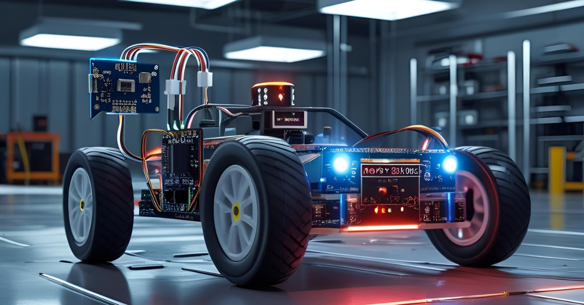
🧠 Tech Stack:
- Microcontroller: Arduino Uno (or Arduino Nano for a more compact design)
- Sensor:
- Ultrasonic Sensor (HC-SR04): The primary sensor for distance measurement and obstacle detection.
- Optional: Servo Motor (SG90) to mount the ultrasonic sensor on, allowing it to scan left and right for obstacles.
- Motor Driver:
- L298N Motor Driver Module: A dual H-bridge driver capable of controlling two DC motors, allowing for forward, backward, and turning movements.
- Motors:
- 2 or 4 DC Gear Motors: Standard yellow TT motors are commonly used for small robot cars.
- Chassis:
- 2-wheel drive or 4-wheel drive robot car chassis: A sturdy base to mount all components, with wheels and often a caster wheel for stability.
- Power Supply:
- 9V battery: For the Arduino board.
- Separate Battery Pack (e.g., 4x AA batteries or a small LiPo): For the motors, connected to the L298N. Motors require more current than the Arduino can supply.
- Wiring: Jumper wires, breadboard (for prototyping).
📦 Project Overview & Concept:
The Real-Time Object Avoiding Car is an entry-level autonomous robotics project that demonstrates fundamental principles of sensor-based navigation and real-time control. The core concept is to build a mobile robot that can detect obstacles in its path and autonomously adjust its trajectory to avoid collisions.
The system operates on a continuous feedback loop:
1. Environment Sensing: The Ultrasonic Sensor (HC-SR04) acts as the car's "eyes." It emits ultrasonic sound waves and measures the time it takes for those waves to bounce off an object and return. This time difference is used to calculate the distance to the nearest obstacle in front of the car. If a servo motor is used, the ultrasonic sensor can sweep left and right to get a broader view of the surroundings.
2. Decision Making (Automation Logic): The Arduino microcontroller is the car's "brain."
- It continuously reads the distance data from the ultrasonic sensor.
- Based on a pre-defined "threshold distance" (e.g., 20 cm), the Arduino determines if an obstacle is too close.
- If an obstacle is detected within the threshold, the Arduino executes a pre-programmed avoidance routine (e.g., stop, look left/right, turn in the clear direction, or reverse and then turn).
- If no obstacle is detected, the car continues moving forward.
3. Motion Control: The L298N Motor Driver acts as the "muscle controller."
- The Arduino sends control signals (PWM for speed, digital signals for direction) to the L298N.
- The L298N, in turn, provides the necessary power to the DC motors to make the car move forward, backward, left, or right, or stop according to the Arduino's commands.
This project is a classic for understanding the interplay between sensors, logic, and actuators in creating autonomous behavior.
📈 Why Build It: Benefits & Impact
Building a Real-Time Object Avoiding Car in 2025 provides significant practical and conceptual benefits:
- A Classic Robotics Project: This is a fundamental and widely recognized robotics project. Mastering it provides a strong foundation for more complex autonomous systems.
- Understanding Sensors & Actuators: You gain direct experience with how sensors (ultrasonic) provide input to a system and how actuators (motors via a driver) execute commands based on that input.
- Real-Time Decision Making: The project teaches you how to implement basic real-time logic. The car needs to react instantly to environmental changes, which is a critical concept in robotics and automation.
- Motor Control Fundamentals: You'll learn how to interface with and control DC motors, including forward/reverse direction and basic speed control using PWM, via a motor driver. This is a core skill for any moving robot.
- Basic Autonomous Navigation Logic: You'll design and implement simple algorithms for obstacle avoidance, which is a building block for advanced path planning and navigation systems.
- Problem-Solving & Debugging: Troubleshooting issues like sensor inaccuracies, motor wiring problems, power delivery, and logic errors will significantly enhance your debugging and critical thinking skills.
- Tangible & Visually Appealing Project: A moving robot that smartly avoids obstacles is highly engaging and makes for an excellent demonstration piece in your portfolio or during interviews. It clearly shows your ability to bring an idea from concept to a working physical system.
- Foundation for Advanced Robotics: The skills learned here (sensor integration, motor control, autonomous logic) are directly transferable to more complex projects like line-following robots, SLAM (Simultaneous Localization and Mapping) robots, or even industrial automation vehicles.
🚗 Use Cases:
While primarily an educational project, the principles of an object-avoiding car have numerous real-world applications and serve as a stepping stone for:
- Educational & Hobbyist Robotics:
- A perfect introductory project for students and enthusiasts in robotics clubs, STEM programs, and self-learning.
- Used in robot competitions (e.g., line following with added obstacle avoidance).
- Autonomous Mobile Robots (AMRs) in Industry:
- The fundamental logic is applied in larger scale AMRs used in warehouses and factories for material transport, where they need to navigate dynamic environments and avoid collisions with people or other equipment.
- Automated Guided Vehicles (AGVs):
- Early forms of AGVs for simple material handling often relied on similar obstacle detection principles.
- Security & Surveillance Robots:
- Simple patrolling robots might use similar sensor arrays to navigate an area without bumping into furniture or walls.
- Vacuum Cleaning Robots:
- Consumer robot vacuums use a combination of ultrasonic, infrared, and bumper sensors for obstacle detection and room navigation.
- Exploration Robots (e.g., Disaster Zones):
- Small robots sent into dangerous or inaccessible areas might use simple obstacle avoidance to navigate rubble and debris.
- Proof of Concept for Self-Driving Vehicles (Simplified):
- While vastly more complex, the core idea of "sense, process, act" to avoid collisions is a miniature version of what advanced driver-assistance systems (ADAS) and autonomous vehicles do.
This project is a perfect blend of hardware and software, offering a solid entry into the fascinating world of autonomous systems and laying crucial groundwork for future robotics endeavors.
Project 7: Real-Time Object Avoiding Car (Ultrasonic + L298N) Codes:
🔗 View Project Code on GitHubHow to Use and Set Up:
1. Arduino IDE Setup:
- Download and install the Arduino IDE if you haven't already.
- Go to
Tools > Board > Arduino AVR Boardsand selectArduino Uno. - Go to
Tools > Portand select the serial port connected to your Arduino Uno.
2. Install Libraries:
- This project uses basic Arduino functions, so no special libraries are required beyond what's built into the IDE.
3. Wiring:
- Follow the detailed wiring guide provided in the comments within the code.
- Common Ground: Ensure that the GND of your Arduino, the GND of your L298N, and the negative terminal of your motor battery are all connected together. This is crucial for proper operation.
- Separate Power for Motors: You must provide a separate external battery pack (e.g., 4xAA, 9V, or LiPo, depending on your motors' voltage requirements) to the L298N's +12V (or VCC) and GND terminals. Do NOT try to power the motors directly from the Arduino's 5V pin, as it cannot supply enough current.
4. Upload the Code:
- Copy the entire code block into your Arduino IDE.
- Click the "Verify" button (checkmark icon) to compile the code.
- Click the "Upload" button (right arrow icon) to upload the code to your Arduino Uno.
5. Test the Car:
- Power up your Arduino and the L298N motor driver (with its connected motor battery).
- Place the car on a flat surface with some obstacles in front of it.
- The car should start moving forward. As it approaches an obstacle within the
OBSTACLE_DISTANCE_THRESHOLD_CM(default 25cm), it should stop, reverse, and then turn before attempting to move forward again. - Open the Serial Monitor (
Tools > Serial Monitor) with the baud rate set to9600to observe the distance readings and the car's decision-making process.
Next Steps and Improvements:
- Intelligent Turning:
- Scan for Clear Path: Mount the ultrasonic sensor on a small servo motor (SG90). When an obstacle is detected, turn the sensor left, then right, to find the direction with the greatest distance (clearest path). Then, command the robot to turn in that direction. This makes avoidance much more effective.
- PID Control for Motor Speed: For smoother and more consistent movement, especially on turns, explore PID (Proportional-Integral-Derivative) control for motor speed, potentially using encoders on the wheels for feedback.
- Line Following: Integrate line-following sensors (infrared TCRT5000 modules) to make the car follow a line while still being able to avoid obstacles that appear on the line or in its path.
- Bluetooth/IR Remote Control Override: Add an IR receiver or a Bluetooth module (like HC-05) to allow manual control of the robot. The autonomous obstacle avoidance would act as a safety feature, preventing collisions even when manually driven.
- Multiple Sensors: Use multiple ultrasonic sensors or integrate infrared proximity sensors for a wider field of view for obstacle detection.
- Battery Monitoring: Add a voltage divider and analog read to monitor the motor battery level and prevent it from running too low.
- Chassis and Aesthetics: Design and build a custom, more robust, or visually appealing chassis for your robot.
- Advanced Navigation: Explore more advanced navigation algorithms like wall-following or simple maze-solving.
8. Home Security System with GSM & PIR Sensors
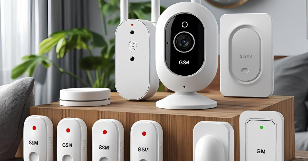
🧠 Tech Stack:
- Microcontroller: Arduino Uno (or Arduino Nano for a more compact final product).
- Sensors:
- PIR (Passive Infrared) Motion Sensor (e.g., HC-SR501): Detects changes in infrared radiation caused by moving objects (like people), indicating presence.
- Optional Sensors for Enhancement:
- Door/Window Reed Switches: Detect when a door or window is opened.
- Vibration Sensor (SW-420): Detects forceful entry or breaking glass.
- Sound Sensor: To detect loud noises (e.g., glass breaking).
- Communication Module:
- GSM Module (e.g., SIM800L, SIM900A): Enables the system to send SMS messages and potentially make calls over the cellular network. Requires a valid SIM card with credit/plan.
- Output Devices:
- Buzzer/Small Siren: For an audible alarm when an intrusion is detected.
- LEDs: For system status indication (e.g., armed, disarmed, motion detected, GSM connected).
- User Interface (Optional for Arm/Disarm):
- Keypad (e.g., 4x4 Membrane Keypad): To enter a PIN for arming/disarming the system.
- Push Button/Toggle Switch: Simple arm/disarm mechanism.
- Power Supply:
- 9V battery or a dedicated power adapter for the Arduino.
- Separate, robust power supply (e.g., 5V, 2A adapter) for the GSM module, as it draws significant current spikes during transmission.
- SIM Card: A working SIM card from any cellular provider.
📦 Project Overview & Concept:
The Home Security System with GSM & PIR Sensors is an affordable yet highly effective solution designed to protect premises by detecting unauthorized entry and alerting the owner in real-time, regardless of their location. It provides a foundational understanding of practical security systems.
The core concept operates as follows:
- Motion Detection: One or more PIR Motion Sensors are strategically placed in areas prone to intrusion (e.g., near entrances, hallways). These sensors constantly monitor for changes in infrared patterns, which occur when a warm body (like a human) moves within their detection range.
- System Arming/Disarming: The system can be manually armed or disarmed using a simple button, toggle switch, or a numerical keypad (for PIN-based access). When armed, the system actively monitors sensor inputs.
- Intrusion Detection & Alert Trigger:
- When the system is armed, and a PIR sensor detects motion, the Arduino registers this as a potential intrusion.
- Upon detection, the Arduino immediately triggers a local alarm (via a buzzer/siren) to deter the intruder and alert anyone nearby.
- Real-time SMS Notification (GSM Module):
- Crucially, the Arduino then activates the GSM Module.
- The GSM module, using the inserted SIM card, sends pre-configured SMS alert messages to one or more designated phone numbers (e.g., the homeowner, family members, or security personnel).
- The SMS message can include details like "Motion detected at front door!" or "Intruder Alert!" along with a timestamp.
- Status Indication: LEDs provide visual cues on the system's status (e.g., green for armed, red for motion detected, blue for GSM network activity).
This project combines embedded sensing, basic security logic, and critical cellular communication, making it a highly practical and impactful build.
📈 Why Build It: Benefits & Impact
Building a Home Security System with GSM & PIR Sensors in 2025 offers numerous benefits that are highly valued in the job market:
- Real-World Relevance & High Demand: Security is a perennial concern for homes and businesses. This project addresses a fundamental need, making it extremely relevant and impactful. It's a tangible application of embedded systems in everyday life.
- Mastering Cellular Communication (GSM): This is a key learning curve. You'll understand how to interface with a GSM module, send AT commands, manage network registration, and reliably send SMS messages. This skill is vital for IoT projects requiring wide-area connectivity where Wi-Fi isn't available.
- Sensor Integration & Thresholding: You'll gain hands-on experience with PIR sensors, understanding their operation, sensitivity, and how to programmatically interpret their output for event detection.
- Alarm System Logic: You'll develop the core logic for an alarm system, including arm/disarm states, delay timers, and alert triggering. This provides a foundation for more complex control systems.
- Robustness & Reliability: Designing a security system requires attention to reliability, error handling (e.g., GSM network issues), and power management, which are crucial embedded development skills.
- Problem-Solving & Debugging: Troubleshooting GSM module initialization, signal strength issues, and timing for motion detection will significantly enhance your debugging prowess.
- Cost-Effective Solution: Compared to commercial security systems, a DIY Arduino-based system is much more affordable, demonstrating practical application of embedded tech for budget-conscious solutions.
- Portfolio Differentiator: A functional security system is a powerful addition to your portfolio. It showcases your ability to build a complete, practical, and critical application of embedded systems, appealing to employers in smart home, security, IoT, and general embedded software/hardware roles.
🏠 Use Cases:
The applications of a Home Security System with GSM & PIR Sensors are straightforward and impactful:
- Residential Security:
- Home/Apartment Security: The primary use case, alerting homeowners to intruders.
- Garage/Shed Monitoring: Secure outbuildings where Wi-Fi might not reach, but cellular signal is present.
- Vacation Homes: Monitor properties remotely when unoccupied.
- Small Business/Office Security:
- Shop/Office Surveillance: Provide an affordable security layer for small retail outlets or offices after hours.
- Warehouse/Storage Unit Monitoring: Alert owners to unauthorized access in storage facilities.
- Remote Monitoring in Areas with No Wi-Fi:
- Construction Sites: Monitor equipment or tools during off-hours.
- Farm Buildings/Barns: Alert farmers to activity in remote agricultural structures.
- Boats/RVs: Security for vehicles or vessels parked in remote locations.
- Assisted Living/Elderly Care:
- Fall Detection (with additional sensors like accelerometers) / Activity Monitoring: While primarily for intrusion, the concept can be adapted to send alerts if no activity is detected for an extended period, or if a specific event (like a fall) occurs.
- Prototype for Commercial Systems:
- Serves as a fundamental prototype for more advanced, professional security systems that might integrate with central monitoring stations.
- Emergency Alert System:
- With a simple modification, the GSM module could be triggered by other events (e.g., a smoke detector or a panic button) to send emergency SMS alerts.
This project is a perfect demonstration of how simple, low-cost embedded hardware can provide significant real-world utility and peace of mind, making it an excellent showcase for your engineering capabilities.
Project 8: Home Security System with GSM & PIR Sensors Codes:
🔗 View Project Code on GitHubHow to Use and Set Up:
1. Arduino IDE Setup:
- Download and install the Arduino IDE if you haven't already.
- Go to
Tools > Board > Arduino AVR Boardsand selectArduino Uno. - Go to
Tools > Portand select the serial port connected to your Arduino Uno.
2. Install Libraries:
- This project uses the
SoftwareSeriallibrary, which is built into the Arduino IDE, so no extra installation is needed.
3. Create a GSM Module Power Supply:
- This is the most critical part. GSM modules (like SIM800L/SIM900A) draw significant current spikes (up to 2A) when transmitting, which the Arduino's 5V pin cannot provide.
- You must use a separate, dedicated power supply for the GSM module. This can be a 5V 2A (or higher amperage) wall adapter or a suitable battery pack (e.g., a LiPo battery with a buck converter to provide stable 4.2V-5V for the GSM module).
- Connect the positive output of this power supply to the GSM module's VCC/5V pin and its negative output to the GSM module's GND.
4. Wiring:
- Follow the detailed wiring guide provided in the comments within the code.
- Crucial: Ensure a common ground between your Arduino Uno, the GSM module, and its dedicated power supply. Connect all GND pins together.
- Upload Disconnection: Before uploading the code to your Arduino, disconnect the TXD and RXD pins of the GSM module from Arduino Digital Pins 4 and 5. These pins are used for serial communication during upload and can interfere. Reconnect them after the code is successfully uploaded.
5. Insert SIM Card:
- Carefully insert a working SIM card (from any cellular provider) into the GSM module. Ensure it has sufficient credit or an active plan to send SMS messages.
6. Configure Phone Number:
- In the provided Canvas code, locate the line:
C++
const char* alertPhoneNumber = "YOUR_PHONE_NUMBER";
- Replace
"YOUR_PHONE_NUMBER"with the actual phone number (including international dialing code, e.g.,"+1234567890") to which you want to send SMS alerts. Make sure to keep the double quotes.
7. Upload the Code:
- Copy the entire code block into your Arduino IDE.
- Click the "Verify" button (checkmark icon) to compile the code.
- Click the "Upload" button (right arrow icon) to upload the code to your Arduino Uno.
8. Test the System:
- After uploading, reconnect the GSM module's TXD/RXD pins to Arduino Pins 4/5.
- Power up the Arduino and the GSM module.
- Open the Serial Monitor (
Tools > Serial Monitor) with the baud rate set to9600. - You should see messages indicating "GSM Serial Initialized." and "GSM Module Ready."
- The system will arm initially and the green "Armed" LED should light up.
- Wait for a few seconds for the GSM module to fully register with the cellular network (its network status LED usually blinks slowly once connected).
- Move your hand in front of the PIR sensor.
- The red "Alert" LED should turn on, the buzzer should sound, and you should receive an SMS message on the configured phone number saying "ALERT: Motion detected at your home!".
- The system will re-arm after 10 seconds if not disarmed via the button. Pressing the button will toggle the system's armed state.
Next Steps and Improvements:
- Multiple Sensors & Zones:
- Integrate more PIR sensors for wider coverage.
- Add door/window reed switches to detect openings.
- Use vibration sensors to detect glass breaking or forced entry.
- Define "zones" and include zone information in the SMS alerts (e.g., "Motion detected in Living Room!").
- Arm/Disarm Methods:
- Keypad: Add a 4x4 membrane keypad for PIN-based arming/disarming. This provides better security than a simple button.
- RFID/NFC: Use an RFID reader to arm/disarm with a tag, similar to the Smart Attendance System.
- SMS Commands: Implement functionality to arm or disarm the system by sending specific SMS commands to the GSM module.
- Two-Way Communication:
- Allow the system to respond to SMS queries (e.g., "STATUS" to get current armed state, "READ SENSORS" to get current PIR status).
- Local Storage:
- Add an SD card module to log events (motion detection, arm/disarm times, SMS sent) for auditing purposes.
- Battery Backup:
- Implement a battery backup system (e.g., a LiPo battery with charging/discharge management circuit) for both the Arduino and the GSM module, so the system remains operational during power outages.
- Cloud Integration (IoT Platform):
- While GSM provides direct alerts, integrating with an IoT platform (e.g., Thingspeak, Adafruit IO, or a custom web server) can provide a comprehensive dashboard for monitoring system status, sensor readings, and alert history. This would require an ESP32/ESP8266 instead of Arduino Uno.
- Siren/Loud Alarm:
- Replace the small buzzer with a louder 12V siren (controlled via a transistor or a higher-current relay) for a more effective deterrent.
- False Alarm Prevention:
- Implement more sophisticated logic: e.g., requiring two PIR sensors to trigger within a short time, or a delay before the alarm sounds and SMS is sent, giving time for a legitimate user to disarm.
- Image Capture:
- For advanced systems, integrate a small camera module (e.g., ESP32-CAM) to capture an image upon motion detection and send it to an email or cloud storage (requires more processing and potentially cloud integration).

🚀 Ready to turn your passion for hardware into real-world innovation?
At Huebits, we don’t just teach Embedded Systems — we train you to build smart, connected, real-time solutions using the tech stacks that power today’s most advanced devices.
From microcontrollers to IoT deployments, you’ll gain hands-on experience building end-to-end systems that sense, compute, and communicate — built to thrive in the field, not just on paper.
🧠 Whether you're a student, aspiring embedded engineer, or future IoT architect, our Industry-Ready Embedded Systems & IoT Engineering Program is your launchpad.
Master C, Embedded C++, MicroPython, FreeRTOS, ESP32, STM32, and cloud integration with AWS IoT — all while working on real-world projects that demand precision, problem-solving, and execution.
🎓 Next Cohort Starts Soon!
🔗 Join Now and secure your place in the IoT revolution powering tomorrow’s ₹1 trillion+ connected economy.
9. Industrial Machine Monitoring Unit (Vibration + Temp + MQTT)
🧠 Tech Stack:
- Microcontroller: ESP32 (e.g., ESP32-WROOM-32 DevKitC) - Chosen for its powerful dual-core processor, integrated Wi-Fi and Bluetooth, and strong performance for handling sensor data and network protocols.
- Sensors:
- Vibration Sensor (e.g., ADXL345 Accelerometer, or more industrial-grade piezoelectric accelerometers): To detect abnormal vibrations, which can indicate bearing wear, misalignment, or imbalance in machinery. An ADXL345 is good for basic proof-of-concept, but for true industrial applications, a sensor like the MPU-6050 (accelerometer + gyroscope) or specialized industrial accelerometers would be considered.
- Temperature Sensor (e.g., DS18B20, LM35, or a K-type Thermocouple with MAX6675/MAX31855 amplifier): To monitor the operating temperature of machine components (motors, bearings, gearboxes). Elevated temperatures are often a precursor to failure.
- Optional Sensors for Comprehensive Monitoring:
- Current Sensor (e.g., ACS712): To monitor motor current draw, indicating load changes or mechanical issues.
- Sound Sensor: To detect abnormal noises from machinery.
- Dust Sensor: For monitoring air quality in certain industrial environments.
- Communication Protocol:
- MQTT (Message Queuing Telemetry Transport): A lightweight, publish-subscribe messaging protocol ideal for IoT devices with limited resources and often unreliable networks. It's the standard for sending telemetry data to the cloud.
- Cloud Platform:
- AWS IoT Core: Amazon Web Services' managed cloud service for connecting IoT devices to the AWS cloud. It provides secure device communication, data routing, and integration with other AWS services. (Alternatives: Google Cloud IoT Core, Azure IoT Hub, Adafruit IO, Thingspeak).
- Backend & Frontend (for data visualization & alerts):
- AWS Services (for a complete solution): AWS IoT Analytics for data processing, AWS Lambda for serverless function triggers (e.g., sending alerts), Amazon DynamoDB or S3 for data storage, Amazon QuickSight or Grafana for dashboarding and visualization.
- MQTT Broker (for local/testing): Mosquitto (open-source) can be used initially before moving to a cloud broker.
- Power Supply: Robust industrial-grade power supply for the ESP32 and sensors, potentially leveraging machine's existing power or a reliable external source.
📦 Project Overview & Concept:
The Industrial Machine Monitoring Unit is a critical component of a modern smart factory, designed to enable predictive maintenance and enhance operational efficiency. It moves beyond traditional reactive maintenance (fixing things after they break) to a proactive approach, identifying potential machine failures before they occur.
The core concept involves:
- Edge Data Acquisition: The ESP32 unit, strategically mounted on or near a factory machine (e.g., a motor, pump, conveyor belt), continuously collects critical operational data from its attached sensors.
- Vibration Data: The vibration sensor monitors the machine's characteristic vibrations. Deviations from normal vibration patterns (e.g., increased amplitude, specific frequency changes) can indicate wear, misalignment, or bearing damage.
- Temperature Data: The temperature sensor measures the machine's surface or internal temperature. Unexpected temperature rises are often a sign of friction, overheating, or impending mechanical failure.
- Edge Processing & Filtering (Optional but recommended): The ESP32's processing power allows for basic data filtering, aggregation, or even simple anomaly detection right at the "edge" (on the device). This reduces the amount of data sent to the cloud, saving bandwidth and processing costs. For instance, instead of sending raw vibration readings, it might send the RMS (Root Mean Square) value or trigger data only when a threshold is exceeded.
- Secure Cloud Communication (MQTT to AWS IoT): The collected (and potentially pre-processed) sensor data is then securely transmitted to the cloud using the MQTT protocol. The ESP32 acts as an MQTT client, publishing data to an AWS IoT Core topic. AWS IoT Core provides secure, bidirectional communication between the devices and the cloud.
- Cloud Data Ingestion & Analytics: Once the data reaches AWS IoT Core, it can be routed to various other AWS services for:
- Storage: Storing raw and processed data in databases (DynamoDB) or data lakes (S3).
- Real-time Analytics: Using services like AWS IoT Analytics to perform complex analysis, identify trends, detect anomalies, and trigger alerts.
- Visualization: Creating custom dashboards (e.g., using Amazon QuickSight or Grafana) to visualize machine health, historical trends, and alarm states for operators and maintenance personnel.
- Anomaly Detection & Alerting: The cloud-based analytics engine constantly monitors incoming data against predefined thresholds or machine learning models (trained on historical normal operation data). If an anomaly (e.g., sudden temperature spike, sustained high vibration) is detected, the system triggers alerts (e.g., SMS, email, dashboard notifications) to maintenance teams, enabling them to intervene before a catastrophic failure occurs.
This project is a tangible example of an Industrial Internet of Things (IIoT) solution, transforming raw sensor data into actionable insights for operational efficiency and cost savings.
📈 Why Build It: Benefits & Impact
Building an Industrial Machine Monitoring Unit in 2025 is incredibly valuable and strategically positions you for high-demand roles:
- Core for Industry 4.0 and Predictive Maintenance: This project is a direct application of Industry 4.0 principles. It demonstrates your ability to build systems that contribute to smart factories, automation, and data-driven decision-making, which are crucial for modern industrial environments.
- Mastering MQTT and Cloud IoT Platforms: You'll gain hands-on experience with MQTT, the de-facto standard for IoT messaging, and deeply understand how to integrate embedded devices with powerful cloud platforms like AWS IoT Core. This skill is critical for any scalable IoT solution.
- Sensor Selection & Industrial Data Acquisition: You'll learn about different types of industrial sensors (vibration, temperature) and the challenges of accurately acquiring data in harsh industrial environments.
- Data Pre-processing at the Edge: Understanding how to filter, average, or calculate metrics (like RMS for vibration) on the microcontroller before sending to the cloud is essential for efficiency and reducing cloud costs.
- Understanding Predictive Maintenance Concepts: This project directly teaches the concepts behind predictive maintenance – monitoring machine health parameters to anticipate failures, reduce downtime, and optimize maintenance schedules. This is a highly sought-after capability in manufacturing and industrial sectors.
- Full-Stack IIoT Exposure: While focused on the embedded unit, the project inherently requires understanding the entire IIoT data pipeline – from sensor to cloud ingestion, analytics, and visualization. This gives you a broad, valuable perspective.
- Real-Time Data Handling & Anomaly Detection: You'll work with real-time data streams and learn basic principles of detecting abnormal conditions.
- Problem-Solving in Industrial Context: You'll face challenges related to sensor accuracy, network reliability in industrial settings, power stability, and data integrity, all of which are common in real-world IIoT deployments.
- Highly Impressive Portfolio Project: A working IIoT condition monitoring unit is a standout project. It demonstrates strong capabilities in embedded systems, cloud integration, data analytics, and an understanding of critical industrial applications, making you very attractive to companies in manufacturing, automation, oil & gas, energy, and logistics.
🏭 Use Cases:
The principles and system developed in this project have direct applications across various industrial sectors:
- Manufacturing & Production Plants:
- Motor & Pump Monitoring: Detecting bearing wear, misalignment, or cavitation in motors and pumps used in assembly lines, HVAC systems, or fluid transfer.
- Conveyor Belt Monitoring: Identifying roller issues, belt damage, or motor strain.
- CNC Machines: Monitoring spindle health, vibration during machining, and tool wear.
- Oil & Gas Industry:
- Pipeline Pump Stations: Monitoring the health of pumps and compressors in remote locations to prevent costly downtime.
- Drilling Equipment: Predicting failures in drilling rig components.
- Power Generation & Utilities:
- Turbines & Generators: Monitoring vibration and temperature in critical rotating machinery in power plants.
- Transformers: Detecting overheating or abnormal electrical noise.
- HVAC Systems in Commercial Buildings:
- Monitoring large chillers, air handlers, and pumps to optimize maintenance and prevent costly breakdowns.
- Logistics & Material Handling:
- Forklifts & Automated Guided Vehicles (AGVs): Monitoring motor and transmission health to ensure fleet reliability.
- Conveyor Systems: Predictive maintenance for large-scale conveyor networks in distribution centers.
- Smart Agriculture:
- Monitoring pumps for irrigation systems, fans in greenhouses, or machinery used in automated harvesting.
- Mining:
- Monitoring heavy machinery (excavators, crushers) for early signs of mechanical failure in harsh environments.
This project goes beyond a simple gadget; it's about building a foundational piece of the digital transformation sweeping through industries worldwide.
Project 9: Industrial Machine Monitoring Unit (Vibration + Temp + MQTT) Codes:
🔗 View Project Code on GitHubHow to Use and Set Up:
1. Arduino IDE Setup:
- Download and install the Arduino IDE.
- Install ESP32 Board Manager:
- Go to
File > Preferences. - In "Additional Boards Manager URLs", add:
https://raw.githubusercontent.com/espressif/arduino-esp32/gh-pages/package_esp32_index.json - Go to
Tools > Board > Boards Manager..., search for "esp32", and install "esp32 by Espressif Systems".
- Go to
- Select your ESP32 board:
Tools > Board > ESP32 Arduino > ESP32 Dev Module(or your specific board). - Select the correct
Tools > Portfor your ESP32.
2. Install Libraries:
- Open
Sketch > Include Library > Manage Libraries.... - Search for and install:
PubSubClientby Nick O'LearyArduinoJsonby Benoit Blanchon (Version 6 is recommended, use a compatible version if you encounter issues)Adafruit Unified Sensorby AdafruitAdafruit ADXL345by AdafruitOneWireby Paul StoffregenDallasTemperatureby Miles Burton / Dallas Semiconductor
WiFi.h,WiFiClientSecure.h,Wire.hare built-in for ESP32.
3. AWS IoT Core Setup:
- Create an AWS Account: If you don't have one, sign up for AWS.
- Navigate to AWS IoT Core: Search for "IoT Core" in the AWS Management Console.
- Create a Thing:
- Go to
Manage > Thingsand click "Create things." - Choose "Create a single thing."
- Give it a name (e.g.,
esp32-machine-monitor-001). Click "Next." - Create Certificates (Crucial Step): Select "One-click certificate creation (recommended)."
- Download Certificates: On the next screen, download all four files:
- A certificate for this thing (e.g.,
xxxx.cert.pem) - A private key file (e.g.,
xxxx.private.key) - A public key file (optional for this project, but download it)
- Amazon Root CA certificate: Download the recommended CA for AWS IoT. You can find the latest version here. A common one is
AmazonRootCA1.pem.
- A certificate for this thing (e.g.,
- Activate Certificate: Make sure to activate the certificate.
- Attach Policy: Click "Attach a policy" and either:
- Create a new policy (e.g.,
iot_publish_policy) withiot:Publishpermission for yourMQTT_TOPIC_PUB(e.g.,arn:aws:iot:YOUR_REGION:YOUR_ACCOUNT_ID:topic/machine/sensor_data). For simplicity during development, you can allowiot:Publishon*topics, but restrict it for production. - Attach an existing policy if you have one.
- Create a new policy (e.g.,
- Register Thing: Click "Register thing."
- Find Your AWS IoT Endpoint: Go to
Settingsin the AWS IoT Core console. Copy your "Device data endpoint."
4. Configure Code with Credentials and Certificates:
- Open the Canvas code in Arduino IDE.
- Wi-Fi: Replace
YOUR_SSIDandYOUR_PASSWORDwith your Wi-Fi credentials. - AWS IoT Endpoint: Replace
YOUR_AWS_IOT_ENDPOINTwith the endpoint you copied from AWS IoT Core Settings. - Certificates:
- Open the
xxxx.cert.pem,xxxx.private.key, andAmazonRootCA1.pemfiles you downloaded in a text editor. - Copy the content (including
-----BEGIN...and-----END...lines) into the respectiveAWS_CERT_CA,AWS_CERT_CRT, andAWS_PRIVATE_KEYvariables in the code. Ensure the exact formatting (including newlines and hyphens) is maintained within theR"EOF(...)EOF"blocks. - MQTT Client ID: You can keep the default
esp32-machine-monitor-001or change it. It must be unique for each device connecting to AWS IoT. - MQTT Topic: You can keep
machine/sensor_dataor change it. Ensure your AWS IoT policy allows publishing to this topic.
5. Wiring:
- Follow the detailed wiring guide in the comments within the code for your ADXL345 and DS18B20 sensors to the ESP32.
- Remember the 4.7K Ohm pull-up resistor for the DS18B20 data line.
6. Upload the Code:
- Click the "Verify" button (checkmark icon) to compile the code.
- Click the "Upload" button (right arrow icon) to upload the code to your ESP32.
7. Monitor and Verify:
- Open the Serial Monitor (
Tools > Serial Monitor) with the baud rate set to115200. - Observe the ESP32 connecting to Wi-Fi and then to AWS IoT Core.
- You should see messages indicating "Publish successful" and the JSON payload being printed.
- Verify in AWS IoT Core:
- Go to
Test > MQTT test client. - In the "Subscribe to a topic" tab, enter your
MQTT_TOPIC_PUB(e.g.,machine/sensor_data). - Click "Subscribe." You should start seeing the JSON sensor data published from your ESP32 in real-time.
Next Steps and Improvements:
- Advanced Vibration Analysis:
- FFT (Fast Fourier Transform): Instead of just RMS/Peak-to-Peak, collect higher-rate raw accelerometer data and perform FFT on the ESP32 (requires a dedicated FFT library and more processing) or send raw data to AWS IoT to perform FFT in the cloud (e.g., using AWS Lambda or IoT Analytics). This allows for much more precise anomaly detection (e.g., identifying specific bearing frequencies).
- Feature Extraction: Extract more features from vibration data like kurtosis, crest factor, skewness.
- Edge Anomaly Detection:
- Implement simple threshold-based anomaly detection directly on the ESP32. If a temperature or vibration metric exceeds a predefined "safe" threshold, trigger an immediate local alarm (LED, buzzer) and send a high-priority alert to AWS IoT.
- For more advanced edge AI, explore TinyML models for anomaly detection on sensor data.
- Other Sensors for Comprehensive Monitoring:
- Current Sensor (e.g., ACS712): Monitor motor current draw to detect load changes, mechanical binding, or electrical faults.
- Acoustic Sensor: Listen for abnormal noises from machinery.
- Pressure Sensors: For hydraulic or pneumatic systems.
- RPM/Speed Sensors: To monitor rotational speed.
- Local Data Storage:
- Add an SD card module to the ESP32 to log sensor data locally. This provides redundancy in case of network outages and can store more granular data than what's sent to the cloud.
- AWS IoT Integration & Data Pipeline:
- AWS IoT Rules: Create AWS IoT rules to route incoming MQTT messages to other AWS services:
- AWS IoT Analytics: For advanced data processing, transformations, and anomaly detection.
- Amazon DynamoDB: For storing time-series sensor data for real-time dashboards.
- Amazon S3: For long-term cold storage of raw data.
- AWS Lambda: To trigger actions like sending email/SMS alerts (via SNS) when anomalies are detected.
- Dashboarding: Build a visualization dashboard using AWS QuickSight, Amazon Managed Grafana, or a custom web application (e.g., React with Amplify) to display machine health, trends, and alerts.
- AWS IoT Rules: Create AWS IoT rules to route incoming MQTT messages to other AWS services:
- OTA (Over-the-Air) Updates:
- Implement OTA functionality for your ESP32 so you can deploy firmware updates wirelessly, which is essential for remote industrial deployments.
- Robust Power Supply & Enclosure:
- For industrial environments, ensure a robust, isolated, and stable power supply.
- Design a durable, dust-proof, and potentially vibration-dampening enclosure for the unit.
- Security Hardening:
- Beyond TLS, implement more robust device authentication and authorization on AWS IoT.
- Ensure secure storage of certificates on the device.
- Firmware Optimization:
- Optimize the sampling rate and MQTT publishing frequency to balance data granularity with power consumption and cloud costs.
- Implement ESP32's deep sleep or light sleep modes if battery power is a concern.
This project, especially when expanded, provides a comprehensive demonstration of skills highly sought after in the Industry 4.0 and IIoT sectors.
10. AI-Powered Face Detection System Using Raspberry Pi + OpenCV
🧠 Tech Stack:
- Single-Board Computer (SBC): Raspberry Pi (Recommended: Raspberry Pi 4 Model B for better processing power, or Raspberry Pi 3B+ as a minimum. Consider Raspberry Pi Zero 2 W for ultra-compact, low-power applications if performance is less critical).
- Camera Module: Raspberry Pi Camera Module (v2 or v3 for better resolution and low-light performance). A USB webcam can also be used.
- Programming Language: Python 3 (The de-facto standard for AI/ML development on Raspberry Pi).
- Computer Vision Library: OpenCV (Open Source Computer Vision Library) - The core library for image processing and computer vision tasks.
- Machine Learning Model/Algorithm:
- Haar Cascades: For traditional, fast, and relatively lightweight face detection (e.g.,
haarcascade_frontalface_default.xml). This is excellent for learning and works well on Raspberry Pi. - Optional for More Robust/Advanced Detection:
- DNN (Deep Neural Network) models: Such as MobileNet SSD (Single Shot MultiBox Detector) or YOLO (You Only Look Once) pre-trained for face detection. These offer higher accuracy and robustness but require more processing power, potentially leveraging the Pi's GPU or an additional AI accelerator (e.g., Google Coral USB Accelerator).
- Haar Cascades: For traditional, fast, and relatively lightweight face detection (e.g.,
- Operating System: Raspberry Pi OS (formerly Raspbian) - A Debian-based Linux distribution optimized for the Raspberry Pi.
- Optional Hardware/Peripherals:
- Display: Small HDMI monitor or an official Raspberry Pi touch display for direct output. (Alternatively, access via SSH and VNC for headless operation).
- Power Supply: Official Raspberry Pi power adapter (critical for stability, especially Pi 4).
- Networking: Wi-Fi (built-in) or Ethernet for remote access and potentially sending data/alerts.
- Enclosure: Custom 3D-printed case or off-the-shelf enclosure.
📦 Project Overview & Concept:
The AI-Powered Face Detection System Using Raspberry Pi + OpenCV is an exciting project that brings the power of artificial intelligence and computer vision to an embedded platform. The core concept is to create a compact, low-cost system capable of identifying human faces within a live video stream, performing its computations directly on the "edge" device (the Raspberry Pi) rather than relying on constant cloud connectivity.
The system workflow typically involves:
- Video Stream Acquisition: The Raspberry Pi Camera Module continuously captures video frames from its environment. These frames are essentially a series of images.
- Image Pre-processing: As each frame is captured, OpenCV is used to perform necessary pre-processing steps, such as converting the image to grayscale (which is sufficient for many detection algorithms and reduces computational load).
- Face Detection Algorithm:
- Haar Cascades: The pre-trained Haar Cascade classifier (e.g., for frontal faces) is loaded. This classifier contains a series of XML files that define patterns corresponding to facial features. OpenCV's
detectMultiScalefunction applies this cascade to the processed image, efficiently scanning for regions that match the learned facial patterns. - DNN Models (Advanced): If using a DNN, the pre-trained model (e.g., Caffe or TensorFlow Lite model) is loaded. The image is resized and normalized to fit the model's input requirements, and then passed through the neural network for inference, which outputs bounding boxes and confidence scores for detected faces.
- Haar Cascades: The pre-trained Haar Cascade classifier (e.g., for frontal faces) is loaded. This classifier contains a series of XML files that define patterns corresponding to facial features. OpenCV's
- Real-Time Visualization & Output:
- For each detected face, OpenCV draws a bounding box (rectangle) around it on the live video feed, which can be displayed on a connected monitor.
- The system can also log events (e.g., "Face detected at [timestamp]") to a file, send alerts (e.g., email, push notification, MQTT message), or trigger other actions based on detection.
- Crucially, this processing happens in real-time or near real-time, meaning the detection happens as the video is being captured, without significant delay.
This project is a perfect blend of hardware (Raspberry Pi), software (Python, OpenCV), and machine learning, demonstrating local AI inference capabilities.
📈 Why Build It: Benefits & Impact
Building an AI-Powered Face Detection System in 2025 offers highly valuable skills and portfolio differentiators:
- Combines Edge AI with Embedded Hardware: This is the most significant benefit. You gain hands-on experience deploying AI/ML models directly onto resource-constrained embedded devices. "Edge AI" is a rapidly growing field, crucial for applications requiring low latency, privacy, and reduced bandwidth usage.
- Mastery of Computer Vision (OpenCV): You'll become proficient with OpenCV, the industry-standard library for computer vision. This includes skills like image acquisition, pre-processing, applying detection algorithms, and drawing overlays.
- Introduction to Machine Learning Deployment: You'll understand the practical steps involved in taking a pre-trained ML model (like Haar Cascades or a DNN) and integrating it into an application running on an embedded system.
- Python for Embedded Systems: Reinforces Python's role not just as a scripting language but as a powerful tool for developing complex applications on Linux-based embedded platforms like the Raspberry Pi.
- Real-Time Processing & Optimization: You'll learn the challenges of achieving real-time performance on embedded hardware and basic optimization techniques (e.g., using grayscale images, optimizing loops).
- Understanding Smart Surveillance & IoT: This project directly relates to the smart surveillance industry and broader IoT applications where local intelligence is required.
- Problem-Solving & Debugging: Troubleshooting camera interfaces, OpenCV installations, model loading errors, and performance bottlenecks will significantly sharpen your debugging and system optimization skills.
- Highly Impressive Portfolio Project: A working AI-powered system is incredibly impactful. It demonstrates your ability to work with advanced technologies (AI/ML), integrate complex libraries (OpenCV), and develop solutions on embedded hardware, making you a top candidate for roles in robotics, AIoT, smart security, and embedded vision.
🕵️♀️ Use Cases:
The AI-Powered Face Detection System, while a foundational project, has numerous practical and conceptual applications:
- Smart Surveillance & Security:
- Intruder Detection: Detect human presence in restricted areas and trigger alerts.
- Entry Monitoring: Count people entering/exiting a building (though not identification).
- Pet/Child Monitoring: Detect if a child or pet is in an unsupervised area.
- Home Automation:
- Presence Detection: Turn on lights or adjust thermostats when a face is detected in a room.
- Automated Greetings (Basic): Trigger a pre-recorded message when a familiar face is detected (if combined with face recognition, which is a step beyond detection).
- Retail & Analytics:
- Footfall Counting: Count the number of customers entering a store or a specific aisle.
- Audience Engagement: (Ethically used) detect if people are looking at a digital advertisement.
- Robotics & Human-Robot Interaction (HRI):
- Robot Navigation: Help a mobile robot identify and potentially follow/interact with humans in its environment.
- Social Robotics: A foundational step for robots to acknowledge human presence.
- Access Control (Conceptual, with Recognition):
- The detection system is the first step for more advanced face recognition systems that could grant access based on identity.
- Educational Tool:
- An excellent hands-on project for teaching computer vision, embedded programming, and introductory AI concepts to students.
- Interactive Art Installations:
- Triggering visual or auditory effects based on detecting a viewer's face.
This project is a tangible demonstration of cutting-edge technology, preparing you for roles at the intersection of AI, IoT, and embedded systems, which are driving the next wave of technological innovation.
Project 10: AI-Powered Face Detection System Using Raspberry Pi + OpenCV Codes:
🔗 View Project Code on GitHubHow to Use and Set Up:
1. Raspberry Pi Setup:
- Install Raspberry Pi OS: Ensure you have the latest Raspberry Pi OS (formerly Raspbian) installed on your Raspberry Pi.
- Enable Camera Interface: Go to
Menu > Preferences > Raspberry Pi Configuration. Under the "Interfaces" tab, make sure "Camera" is enabled. If using a Pi Camera Module, connect it to the CSI port on your Pi. If using a USB webcam, simply plug it into a USB port. - Update System: Open a terminal and run:
Bash
sudo apt updatesudo apt upgrade -y2. Install Python and Libraries:
- Install Python 3 and pip: Python 3 is usually pre-installed, but ensure pip is available:
Bash
sudo apt install python3 python3-pip -y- Install OpenCV: This is the most time-consuming part. Follow a reliable guide for installing OpenCV on Raspberry Pi. A common method involves compiling from source, but there are pre-built wheel files for certain versions that can speed it up. Here's a common command for a basic install, but depending on your Pi and OS version, you might need more steps:
Bash
# This is a simplified command; full OpenCV install might take hours and more steps.# Consider a more comprehensive guide like: https://pyimagesearch.com/2021/05/03/installing-opencv-on-raspberry-pi-with-pip-and-virtual-environments/
pip3 install opencv-python numpy# If using picamera (recommended for Pi Camera Module performance)
pip3 install picamera# Optional, but helpful for video processing utilities
pip3 install imutils- Locate Haar Cascade File: The
haarcascade_frontalface_default.xmlfile is crucial. It's usually found in your OpenCV installation directory. You can search for it:
Bash
find / -name Once found, either copy it to the same directory as your Python script, or update the CASC_PATH variable in the Python code with its full path. A common path is /usr/local/share/opencv4/haarcascades/haarcascade_frontalface_default.xml.
3. Transfer the Code:
- Create a new Python file on your Raspberry Pi (e.g.,
face_detector.py) and paste the provided Python code into it. - Save the file.
4. Run the Script:
- Open a terminal on your Raspberry Pi.
- Navigate to the directory where you saved
face_detector.py. - Run the script using Python 3:
Bash
python3 face_detector.py- A new window titled "Face Detection" should open, displaying the live video feed. When a human face is detected, a green rectangle will appear around it.
- Press the
qkey on your keyboard to quit the application.
Next Steps and Improvements:
- Advanced Face Detection (Deep Learning):
- MobileNet SSD/YOLO with TensorFlow Lite: Replace Haar Cascades with a more accurate and robust deep learning model like MobileNet SSD or YOLO, converted to TensorFlow Lite format (
.tflite). This often requires installingtensorflowortflite-runtimeand is more computationally intensive but offers better performance in varied lighting/angles. - Google Coral USB Accelerator: For significantly improved real-time performance with DNN models, integrate a Google Coral USB Accelerator. It offloads the inference to a dedicated TPU (Tensor Processing Unit).
- MobileNet SSD/YOLO with TensorFlow Lite: Replace Haar Cascades with a more accurate and robust deep learning model like MobileNet SSD or YOLO, converted to TensorFlow Lite format (
- Face Recognition:
- Beyond just detecting faces, implement face recognition to identify known individuals. This involves:
- Collecting a dataset of known faces.
- Training a face embedding model (e.g., FaceNet, ArcFace) or using a pre-trained one.
- Storing embeddings for known individuals.
- Comparing detected face embeddings to known ones for identification.
- Beyond just detecting faces, implement face recognition to identify known individuals. This involves:
- Event Logging and Notifications:
- Log detected faces (timestamp, location, perhaps a cropped image) to a file or a database.
- Trigger alerts (email, SMS, push notification) when an unrecognized face is detected or a specific person is identified/not identified within a time frame.
- Integrate with MQTT to send detection events to a cloud IoT platform (e.g., AWS IoT, Google Cloud IoT) for remote monitoring and analysis.
- Web Interface/Stream:
- Stream the video feed with detected faces to a web browser using Flask, Django, or a similar web framework. This allows remote viewing and control.
- Headless Operation & Remote Access:
- Configure your Raspberry Pi for headless operation (no monitor connected).
- Access it remotely via SSH for terminal commands and VNC (Virtual Network Computing) for a graphical desktop environment to view the OpenCV window.
- Power Optimization:
- For battery-powered deployments, optimize the script and Raspberry Pi settings for lower power consumption (e.g., reducing camera resolution/framerate, using smaller models, implementing sleep modes).
- Robust Error Handling:
- Add more comprehensive error handling for camera failures, file access issues, and unexpected input.
- User Interface (Local):
- If using a local display, consider adding buttons or touchscreen controls for arming/disarming the system, viewing logs, or changing settings directly on the device.
This project provides an excellent foundation for diving into the exciting world of edge AI, computer vision, and smart surveillance systems.
🏁 Final Word: Embedded Systems Are Eating the World
In 2025, the digital transformation isn't just happening in the cloud or on our screens; it's profoundly reshaping the physical world around us, thanks to embedded systems. From the smallest smart sensor in an agricultural field to the complex control units in an autonomous vehicle, these "silent backbone" technologies are rapidly becoming the intelligence behind every new innovation.
It's no longer enough to simply know how microcontrollers work, how to read a datasheet, or understand an instruction set architecture in theory. The landscape of embedded engineering in 2025 demands a proven ability to build, integrate, and deploy. Employers are looking for individuals who can bridge the gap between theoretical knowledge and practical application—engineers who can translate concepts into tangible, functional solutions that solve real-world problems.
The projects outlined here go far beyond simple LED blinking or basic sensor readings. They are designed to challenge you to:
- Solve Real Problems with Efficient Code: You'll learn to write lean, optimized code that runs effectively on resource-constrained hardware, understanding memory management, timing, and real-time operating systems (RTOS) considerations. This isn't just about functionality; it's about performance and reliability in the most demanding environments.
- Master Clever Hardware Integration: These projects push you to connect diverse components—sensors, actuators, communication modules—and make them work together seamlessly. You'll troubleshoot circuits, manage power delivery, and ensure robust physical connections, understanding that the software is only as good as the hardware it runs on.
- Design for Scalable Architecture: Especially with projects involving cloud integration (like the Weather Station or Machine Monitoring Unit), you'll gain an appreciation for how individual embedded devices fit into larger, more complex IoT ecosystems. This includes understanding communication protocols (MQTT, BLE), data formatting, and the principles of distributed systems.
- Embrace Cross-Disciplinary Skills: You're not just a coder or a circuit designer; you're becoming a versatile engineer who understands the full vertical stack—from the silicon up to the cloud dashboard. This holistic perspective is incredibly valuable.
Whether you're a fresh graduate stepping into the competitive job market, an experienced professional aiming to pivot into cutting-edge fields, or an aspiring entrepreneur dreaming of building the next big thing in smart devices, these projects give you an unfair edge. They are your tangible proof of concept, your working resume, and your conversation starters in any interview.
In a world increasingly driven by intelligent, connected "things," the ability to design and implement robust embedded systems isn't just a skill—it's a superpower. Don't just learn about embedded systems; build with them, and secure your place at the forefront of technological innovation.
🚀 About This Program — Embedded Systems & IoT Engineering
By 2030, smart systems won’t just support life — they’ll run it. From autonomous cars to connected factories, embedded systems are the invisible backbone of our digital age. Every heartbeat monitor, drone, and industrial robot pulses with code written by engineers who know how to blend hardware with intelligence.
🛠️ The problem? Too many programs push outdated theory and give you a dev board and a prayer. The industry doesn’t need button-pressers — it needs architects, builders, and firmware warriors who can design systems that survive the real world.
🔥 That’s where Huebits flips the script.
We don’t train you to understand embedded systems.
We train you to build them.
Welcome to a 6-month, hands-on, industry-calibrated Embedded Systems & IoT Engineering Program — designed to make you hardware-ready and systems-smart from Day One. Whether it’s designing low-power sensor nodes, building RTOS-based applications, or deploying IoT solutions with real-time data flow — this program is built to wire you for the future.
From mastering C, Embedded C++, and MicroPython to deploying systems with ESP32, STM32, and integrating with cloud platforms like AWS IoT — we take you from raw circuit to full-stack embedded innovation.
🎖️ Certification:
Graduate with a Huebits-certified credential — a mark that speaks louder than degrees. Recognized by embedded industry leaders, hardware startups, and IoT visionaries — this isn’t a participation badge. It’s proof you can solder, code, optimize, and deploy under pressure.
📌 Why It Hits Different:
Real-world, edge-to-cloud industry projects
Hardware labs and debugging drills
LMS access for a full year
Job guarantee upon successful completion
💥 Your future team doesn’t care how much datasheet theory you know — they care how fast you can get a system up and running. Let’s give them something unforgettable.
🎯 Join Huebits’ Industry-Ready Embedded Systems & IoT Engineering Program
and build the future, byte by byte, board by board.

🔥 "Take Your First Step into the Embedded Systems Revolution!"
Ready to design, code, and deploy smart hardware that powers the future — from wearables to factories?
Join the Huebits Industry-Ready Embedded Systems & IoT Engineering Program and get hands-on with microcontrollers, real-time systems, IoT protocols, sensor networks, and cloud integrations — using the exact tools and platforms the industry trusts.
✅ Live Mentorship | 🛠️ Project-Driven Learning | ⚙️ Career-Focused Embedded Curriculum