The Future of Smart Industry: Top 10 IoT Projects Revolutionizing Monitoring and Automation

Introduction: Empowering the Modern World with IoT
In an era fundamentally shaped by the demand for real-time data and groundbreaking automation, the Internet of Things (IoT) stands as a pivotal force, driving unprecedented innovation across virtually every sector. This isn't just about connecting devices; it's about creating intelligent ecosystems where everyday objects, machines, and environments can collect, exchange, and act upon information.
The impact of IoT is pervasive and transformative. In industries, it's enhancing safety protocols by continuously monitoring hazardous conditions and alerting personnel instantly. It's optimizing energy consumption in buildings and factories, leading to significant cost savings and reduced environmental impact. In healthcare, IoT is revolutionizing elderly care with proactive fall detection and remote monitoring, fostering greater independence and peace of mind. Moreover, it's pushing the boundaries of agricultural sustainability by enabling precision farming techniques that optimize resource use and boost crop yields.
Across the globe, IoT-driven systems are not merely offering incremental improvements; they are enabling fundamentally smarter, safer, and remarkably more efficient solutions. By seamlessly integrating microcontrollers, diverse sensors, robust cloud platforms, and intelligent alert systems, IoT is building the foundation for a truly connected, intelligent, and autonomous future, transforming how we live, work, and interact with our world.
This document presents a curated list of 10 cutting-edge IoT projects. These examples powerfully illustrate the profound impact achievable through the seamless integration of microcontrollers, diverse sensors, robust cloud platforms, and intelligent alert systems. They collectively showcase how IoT is not just a technological advancement, but a fundamental shift towards a more connected, intelligent, and autonomous future for industries and cities alike.
Table of Contents:
1. 🌾 Smart Agriculture Using IoT and MQTT Protocol
2. 🧠 IoT-Based Smart Workspace with Telegram AI Chatbot
3. 👟 Smart Shoe for the Blind
4. 🏭 MQTT-Based Factory Environment Monitoring
5. ⚡ Transformer Health Monitoring Using IoT
6. 👵 Elderly Fall Detection System
7. 📶 IoT-Based Smart Feeder Monitoring System
8. 🔌 Remote Transformer Health Monitoring
9. 💡 Smart Energy Monitoring System
10. 📊 IoT-Powered Smart Energy Meter Surveillance
1. 🌾 Smart Agriculture Using IoT and MQTT Protocol

Overview: This project revolutionizes traditional farming by transforming it into an intelligent, data-driven agricultural system. It leverages the power of IoT sensors for precise environmental monitoring and automates irrigation based on real-time needs. At its core, a Raspberry Pi serves as the robust central controller, collecting vital agricultural data. It continuously monitors key parameters such as soil moisture levels, ambient temperature, and humidity using specialized sensors like the DHT11 and dedicated Soil Moisture Sensors. The collected environmental data is then seamlessly transmitted in real-time to the ThingSpeak cloud platform, a popular IoT analytics service, utilizing the lightweight and efficient MQTT protocol. Beyond mere data collection, the system is equipped with an intelligent alert mechanism: Twilio is integrated to send immediate SMS alerts to farmers for critical conditions, such as the onset of drought (critically low soil moisture) or potential crop damage due to overheating (excessive temperature). This comprehensive approach empowers farmers with remote monitoring capabilities, enabling smart irrigation decisions and proactive responses to changing environmental conditions, ultimately leading to optimized resource utilization and improved crop yield.
Details:
- Central Processing Unit: The Raspberry Pi (e.g., Raspberry Pi 3 B+, 4, or Zero W depending on processing needs and power constraints) acts as the brain of the system. Its GPIO (General Purpose Input/Output) pins provide the interface for connecting various sensors. The Raspbian OS (now Raspberry Pi OS) provides a stable Linux environment for running Python scripts and managing network connectivity.
- Sensor Integration:
- DHT11 Temperature and Humidity Sensor: This digital sensor provides accurate readings of both ambient air temperature and humidity. It's connected directly to a GPIO pin on the Raspberry Pi, and libraries are used to interface with it and extract data.
- Soil Moisture Sensor: Typically, a resistive or capacitive soil moisture sensor is used. The resistive type measures resistance between two probes, which changes with moisture content. The capacitive type measures the capacitance change. These usually output an analog value, requiring an Analog-to-Digital Converter (ADC) if the Raspberry Pi model doesn't have built-in ADC capabilities (e.g., using an MCP3008 ADC chip with SPI communication for the Pi). The sensor probes are inserted directly into the soil in the farming area.
- Data Communication (MQTT):
- MQTT Protocol: This is a publish-subscribe messaging protocol designed for lightweight messaging on resource-constrained devices and low-bandwidth networks, making it ideal for IoT applications.
- MQTT Client: A Python script running on the Raspberry Pi acts as an MQTT client. It reads data from the sensors, formats it into suitable messages (e.g., JSON payload), and then publishes these messages to specific "topics" on an MQTT broker.
- MQTT Broker: ThingSpeak acts as the MQTT broker in this setup. It provides a platform where your devices can publish data to unique channels (topics), and you can subscribe to these channels to receive data. ThingSpeak also offers direct API keys for publishing data without an explicit MQTT broker setup if preferred, but using MQTT directly is more efficient for continuous streaming.
- Cloud Platform and Visualization (ThingSpeak):
- ThingSpeak Channels: On ThingSpeak, the farmer sets up a "channel" for their farm. Within this channel, "fields" are defined for each data point (e.g., "Soil Moisture," "Temperature," "Humidity").
- Real-time Dashboard: As data streams from the Raspberry Pi to ThingSpeak via MQTT, ThingSpeak automatically updates real-time charts and widgets on the channel's public or private view. This provides a dynamic and intuitive dashboard for farmers to visualize current conditions.
- ThingSpeak React App/Actions: ThingSpeak allows for "ThingSpeak React" apps or "Actions" which can trigger events based on data thresholds. This feature can be used to initiate actions or send notifications directly.
- Alerting System (Twilio):
- Twilio API Integration: The Python script on the Raspberry Pi, or a custom application/ThingSpeak "React" app, integrates with the Twilio API. When programmed thresholds are breached (e.g., soil moisture drops below a critical level, or temperature exceeds a safe limit), the system makes an API call to Twilio.
- SMS Alerts: Twilio then sends an SMS message to the farmer's registered mobile number, notifying them of the critical condition (e.g., "Alert: Soil moisture low in Field A. Consider irrigation!"). This provides immediate awareness and enables timely intervention.
Step-by-Step Procedure:
- Set up Raspberry Pi with Raspbian OS: Install the latest Raspberry Pi OS onto an SD card and configure the Raspberry Pi, ensuring network connectivity (Wi-Fi or Ethernet). Update packages and enable necessary interfaces like GPIO.
- Connect DHT11 and Soil Moisture Sensors to GPIO pins: Physically wire the sensors to the appropriate GPIO pins on the Raspberry Pi, following sensor datasheets. For the soil moisture sensor, if analog output, an ADC converter (like MCP3008) will be needed and connected via SPI.
- Install Libraries and Program MQTT Client in Python: Install required Python libraries (e.g., paho-mqtt for MQTT, Adafruit_DHT for DHT11, and libraries for ADC if used). Write Python scripts to:
- Read sensor data.
- Initialize the MQTT client.
- Connect to the ThingSpeak MQTT broker using channel ID and API key.
- Publish sensor data to the respective ThingSpeak channel fields at regular intervals.
- Configure Twilio API for SMS alerts: Create a Twilio account, obtain your Account SID, Auth Token, and a Twilio phone number. In your Python script (or ThingSpeak React app), write code to use the Twilio client library to send SMS messages when sensor readings cross predefined critical thresholds.
- Create a dashboard on ThingSpeak for real-time visualization: Log into your ThingSpeak account, create a new channel, define fields for soil moisture, temperature, and humidity. Configure visualizations (charts, gauges) to display the incoming data streams from your Raspberry Pi. Set up ThingSpeak Reacts or Apps to trigger Twilio alerts.
Key Technologies Used:
- Raspberry Pi: Low-cost, credit-card-sized computer, serving as the IoT gateway and data processor.
- DHT11 Sensor: Economical digital sensor for measuring temperature and humidity.
- Soil Moisture Sensor: Detects the volumetric water content in soil.
- MQTT (Message Queuing Telemetry Transport): Lightweight, publish-subscribe network protocol for machine-to-machine communication, ideal for IoT.
- Twilio: Cloud communications platform for sending and receiving SMS, voice, and video messages.
- ThingSpeak: Open-source IoT analytics platform service designed to enable users to analyze and visualize live data streams.
Benefits:
- Smart Irrigation: Enables automated or informed irrigation based on actual soil moisture levels, preventing over-watering or under-watering. This significantly conserves water resources.
- Real-time Weather/Soil Alerts: Farmers receive immediate notifications about critical environmental changes, allowing for timely interventions to protect crops from drought, heat stress, or frost.
- Remote Monitoring for Farmers: Provides farmers with the flexibility to monitor their fields from anywhere at any time via a web dashboard or mobile app, eliminating the need for constant physical presence.
- Optimized Resource Utilization: Reduces waste of water, fertilizers, and energy by providing data-driven insights for efficient resource application.
- Increased Crop Yield and Quality: By maintaining optimal growing conditions, the system helps improve crop health, leading to better yields and higher quality produce.
- Data-Driven Decision Making: Historical data collected on ThingSpeak allows farmers to analyze long-term trends, understand seasonal variations, and make more informed decisions for future planting and resource management.
Project 1: Smart Agriculture Using IoT and MQTT Protocol Codes:
🔗 View Project Code on GitHub🧪 Hardware Connections
|
Sensor |
GPIO Pin |
|
DHT11 |
GPIO 4 |
|
Soil
Moisture (DO) |
GPIO 17 |
Make sure to use pull-down resistors where needed. Soil moisture sensor might be analog—use a digital variant or ADC like MCP3008.
📈 ThingSpeak Setup
- Create a channel with 3 fields: Temperature, Humidity, Soil Moisture.
- Get your MQTT credentials from Account > My Profile > MQTT Settings.
📲 Twilio Setup
- Sign up at https://www.twilio.com/
- Get your Account SID, Auth Token, and virtual number
2. 🧠 IoT-Based Smart Workspace with Telegram AI Chatbot

Overview: This innovative project redefines the modern workspace by integrating IoT capabilities with an intuitive AI-powered Telegram chatbot interface. At its core, a Raspberry Pi acts as the central intelligence hub, connecting to various environmental and presence sensors. Specifically, it utilizes temperature sensors to monitor ambient conditions and motion sensors (PIR sensors) to detect occupancy within the workspace. This real-time sensor data allows the system to intelligently automate various workspace elements, such as turning lights on/off based on occupancy, controlling fans for optimal comfort, or even triggering alarms for security purposes. The key differentiator is the seamless interaction via a Telegram chatbot. Users can issue commands to the bot in natural language (e.g., "Turn on the lights," "What's the temperature?"), and the Telegram Bot API facilitates real-time communication, allowing the system to respond to queries, provide status updates, and execute control commands instantly. This setup provides unparalleled remote control, enhances workspace comfort and safety, and offers a highly user-friendly chat-based interface for managing the environment.
Details:
- Central Processing Unit: The Raspberry Pi (e.g., Raspberry Pi 3 B+, 4, or Zero W) is chosen for its versatility, computational power, and extensive GPIO capabilities. It runs a lightweight Linux distribution (Raspberry Pi OS) and hosts the Python scripts that handle sensor readings, logic, and Telegram API interaction.
- Sensor Integration:
- Temperature Sensor (e.g., DHT11/DHT22 or DS18B20): Connected to the Raspberry Pi's GPIO pins, this sensor continuously monitors the ambient temperature and humidity in the workspace. This data can be used for automated fan control or simply to provide real-time environmental information to the user via the chatbot.
- Motion Sensor (e.g., HC-SR501 PIR Sensor): Also connected to GPIO, this sensor detects infrared radiation emitted by moving objects (like humans). It's crucial for occupancy detection, enabling automation of lights and fans based on whether someone is present in the room.
- Actuators (Controlled Devices):
- Lights: Can be controlled via relays connected to the Raspberry Pi, switching AC power to traditional light fixtures, or by integrating with smart lighting systems (e.g., Philips Hue via an API, or Wi-Fi controlled smart bulbs/switches).
- Fans: Similar to lights, fans can be switched on/off via relays based on temperature thresholds or direct chatbot commands.
- Alarms: A buzzer or siren connected via a relay can be triggered for security purposes (e.g., motion detected when the system is armed) or as a notification.
- Communication & Chatbot Interface (Telegram):
- Telegram Bot API: This API is the bridge between the Raspberry Pi system and the Telegram messaging platform. It allows the Python script to receive incoming messages (commands) from users and send outgoing messages (responses, status updates, alerts) to specific chat IDs.
- BotFather: This official Telegram bot is used to create a new bot, obtain its unique API token, and configure basic bot settings (name, description, profile picture).
- Python python-telegram-bot Library: A popular and robust library for simplifying interaction with the Telegram Bot API in Python. It handles polling for updates, parsing messages, and sending responses.
- AI Chatbot Functionality (Optional but Recommended for "AI Chatbot"): While the overview mentions an "AI Chatbot," the basic implementation might just involve rule-based responses (e.g., if command is "turn on lights", then activate relay). For true "AI" capabilities and natural language understanding (NLU), additional integration would be required:
- Natural Language Processing (NLP) Service: Integrating with services like Google Dialogflow, Rasa, or wit.ai would allow the chatbot to understand more complex and varied user commands (e.g., "It's a bit warm in here," "Is anyone in the office?"). The Raspberry Pi would send user messages to the NLP service for intent recognition and entity extraction, then act based on the interpreted intent.
- Automation Logic: The Python script on the Raspberry Pi contains the core logic:
- Continuously reads sensor data.
- Compares sensor data against predefined thresholds (e.g., if temperature > 25°C, turn on fan).
- Monitors for motion detection.
- Listens for incoming Telegram messages.
- Parses Telegram commands (potentially via NLP service).
- Executes actions (e.g., activate relays for lights/fans, send status messages back to Telegram).
Step-by-Step Procedure:
- Install Telegram and Create a Bot using BotFather:
- Download and install the Telegram app on your smartphone or computer.
- Search for @BotFather in Telegram and start a chat.
- Use the /newbot command to create a new bot. Follow the prompts to set a name and username.
- BotFather will provide you with a unique HTTP API Token. Keep this token secure; it's essential for your bot to function.
- Connect Sensors and Actuators to Raspberry Pi GPIO:
- Wire the DHT11/DHT22 sensor (or DS18B20) to the appropriate GPIO pin (e.g., GPIO4 for DHT11).
- Connect the PIR motion sensor to another GPIO pin (e.g., GPIO17).
- Connect relays for lights, fans, and alarms to other GPIO pins (e.g., GPIO23, GPIO24, GPIO25). Ensure proper power supply and current limiting for relays.
- Install Libraries and Write a Python Script to Read Sensor Data:
- On your Raspberry Pi, install necessary Python libraries: pip install RPi.GPIO (for GPIO control), pip install Adafruit_DHT (for DHT sensors), pip install python-telegram-bot (for Telegram API).
- Write Python code to:
- Initialize GPIO pins.
- Read temperature and humidity from the DHT sensor.
- Monitor the state of the PIR motion sensor.
- Define functions to control the relays (turn on/off lights, fans, alarms).
- Integrate Telegram Bot API to Accept User Commands:
- In the Python script, import the telegram.ext module.
- Initialize the Updater with your bot's API token.
- Create CommandHandler objects to listen for specific commands (e.g., /start, /status, /lights_on, /fan_off).
- Define callback functions for each command that will execute the corresponding actions (e.g., turn_lights_on(), get_temperature_status()).
- Add handlers to the Dispatcher and start polling for updates.
- Automate Control Signals Based on Sensor Input and Commands:
- Implement logic within your Python script:
- Automatic Control: If motion is detected and it's daytime, turn on lights. If temperature exceeds X degrees, turn on the fan. If motion is detected when the alarm is armed, trigger the alarm and send an alert via Telegram.
- Chatbot Control: When a user sends a command like /lights_on, call the function to activate the light relay. If /temperature, read the sensor and send the current temperature back to the user via Telegram.
- Implement logic within your Python script:
Key Technologies Used:
- Raspberry Pi: The primary single-board computer acting as the central controller.
- Motion Sensor (PIR): Detects presence and movement for occupancy-based automation.
- Temperature/Humidity Sensor (e.g., DHT11): Monitors environmental conditions for comfort and automation logic.
- Telegram Bot API: The interface for creating and interacting with the chatbot.
- Python: The primary programming language for the system's logic and API integration.
- Relays: Electronic switches controlled by the Raspberry Pi to operate AC-powered devices like lights and fans.
Benefits:
- Remote Workspace Automation: Users can control their workspace appliances from anywhere in the world using their Telegram app, offering unparalleled convenience.
- Enhanced Safety & Comfort:
- Automated lighting based on occupancy saves energy and ensures comfort.
- Temperature-based fan control maintains a pleasant environment.
- Potential for basic security features like motion-triggered alarms.
- Voice/Chat-Based Control: Provides a natural and intuitive way to interact with the smart workspace, making it accessible to a wider range of users, especially if NLP integration is added for true voice command understanding.
- Energy Efficiency: Intelligent automation based on occupancy and environmental conditions leads to significant energy savings by only powering devices when needed.
- Real-time Status Updates: Users can query the system for current temperature, occupancy status, or device states at any time.
Project 2: IoT-Based Smart Workspace with Telegram AI Chatbot Codes:
🔗 View Project Code on GitHub🛠 Hardware Setup
|
Component |
GPIO Pin |
Notes |
|
PIR
Motion |
GPIO 17 |
Detects
motion |
|
DHT11 |
GPIO 4 |
Temp
& humidity |
|
Light
Relay |
GPIO 23 |
Controls
bulb |
|
Fan
Relay |
GPIO 24 |
Controls
fan |
|
Alarm
Relay |
GPIO 25 |
Buzzer
or alert system |
🧪 Test Commands
|
Command |
Function |
|
|
Start
bot and see welcome message |
|
|
Get
temp, humidity, motion status |
|
|
Turn ON
fan |
|
|
Turn OFF
light |
|
|
Trigger
alarm |
⚠️ Final Note
Add this bot as an admin in a private Telegram group if you want multiple people to access it. Also, consider using ngrok or hosting it via cloud for remote access outside your local network.
3. 👟 Smart Shoe for the Blind

Overview: This project introduces a transformative wearable assistive device: a "Smart Shoe" designed to significantly enhance the mobility, safety, and independence of visually impaired individuals. Integrated directly into the shoe, the system employs ultrasonic sensors to provide real-time, proximity-based obstacle detection. As the user walks, these sensors continuously scan the path ahead, identifying potential hazards. When an obstacle is detected, immediate haptic feedback is provided through strategically placed buzzers or vibration motors within the shoe, alerting the user to the obstacle's presence and direction. The core of the system is an ESP32 microcontroller, renowned for its dual-core processing, Wi-Fi, and Bluetooth capabilities, ensuring efficient sensor data processing and communication. Furthermore, the shoe incorporates a GPS module to track the user's location, a critical safety feature. In emergency situations (e.g., if the user gets lost or falls, potentially triggered by a manual button press or an accelerometer-based fall detection system, though not explicitly mentioned, it's a common enhancement), the ESP32 can send location-based SMS alerts to pre-configured emergency contacts via the Twilio API. This comprehensive approach moves beyond traditional white canes, offering a discreet, dynamic, and highly supportive navigation aid, coupled with a vital emergency communication system. The mention of Blynk indicates a potential mobile application interface for caregivers or for more detailed settings/monitoring.
Details:
- Central Processing Unit: The ESP32 microcontroller is an excellent choice for this wearable project due to its compact size, low power consumption, built-in Wi-Fi and Bluetooth capabilities, and sufficient processing power to handle sensor readings and communication protocols.
- Obstacle Detection and Feedback:
- Ultrasonic Sensors (e.g., HC-SR04): Typically, multiple ultrasonic sensors (e.g., 2-3) are strategically mounted on the front and possibly the sides of the shoe. These sensors emit ultrasonic waves and measure the time it takes for the waves to return after hitting an object. This "time-of-flight" is used to calculate the distance to obstacles.
- Haptic Feedback (Buzzers/Vibration Motors): Small, low-power buzzers or eccentric rotating mass (ERM) vibration motors are embedded into the shoe (e.g., in the toe area, on the sides of the foot, or near the ankle). The ESP32 activates specific buzzers/motors to indicate the direction and proximity of an obstacle (e.g., a strong vibration on the right side if an obstacle is detected to the right, increasing frequency/intensity as the obstacle gets closer). This provides non-auditory, intuitive feedback.
- Navigation and Location Tracking:
- GPS Module (e.g., NEO-6M): A compact GPS module is integrated to acquire the user's real-time latitude and longitude coordinates. This data is crucial for emergency alerts and potentially for basic navigation assistance (though full-fledged turn-by-turn navigation is more complex and typically handled by a paired smartphone app).
- Emergency Communication:
- Twilio API Integration: The ESP32 connects to the internet via Wi-Fi. When an emergency is triggered (e.g., via a small, discreet push button on the shoe or a separate wearable device, or if a fall detection algorithm is implemented), the ESP32 sends a request to the Twilio API.
- SMS Alerts with Location Data: Twilio then dispatches pre-configured SMS messages to emergency contacts (family, friends, caregivers). These messages include the user's current GPS coordinates and potentially a link to a mapping service (like Google Maps) for easy location identification.
- Additional Sensor (DS18B20 - Temperature): The inclusion of a DS18B20 temperature sensor is interesting. While not directly related to obstacle detection or navigation for the user, it could serve several purposes:
- Environmental Monitoring: Provide ambient temperature data, potentially useful for caregivers monitoring the user's outdoor conditions.
- Internal Device Monitoring: Monitor the temperature of the internal electronics, alerting to potential overheating issues.
- Battery Management: While not its primary role, temperature can impact battery performance, and monitoring could be a part of a sophisticated power management system.
- Blynk Integration (Optional Mobile App/Dashboard):
- Blynk App: Blynk is an IoT platform that provides a user-friendly mobile app (Android/iOS) and dashboard for controlling hardware and visualizing data.
- Caregiver Interface: A caregiver could use a Blynk dashboard to:
- View the real-time GPS location of the user.
- Monitor the shoe's battery level.
- Receive custom alerts (e.g., if the user strays outside a geofenced area).
- Adjust certain settings if applicable.
- User Interface (Limited): For the visually impaired user, a minimal Blynk interface might offer voice announcements for certain status updates if paired with a smartphone.
Step-by-Step Procedure:
- Attach Ultrasonic Sensors to the front of the shoe: Carefully mount the ultrasonic sensors (e.g., 2-3) on the front of the shoe, ensuring they have an unobstructed view of the path ahead. Consider waterproof enclosures if the shoe is for outdoor use.
- Connect ESP32 with GPS and DS18B20 temperature sensor:
- Wire the ultrasonic sensors' Trig and Echo pins to appropriate ESP32 GPIOs.
- Connect the GPS module's TX and RX pins to ESP32 RX and TX (or software serial pins).
- Connect the DS18B20 sensor to a GPIO pin configured for one-wire communication.
- Connect the buzzers/vibration motors to ESP32 GPIOs via appropriate driver circuits (e.g., transistors) as they often require more current than GPIOs can supply directly.
- Integrate Twilio API for SMS alerts:
- Sign up for a Twilio account and obtain your Account SID, Auth Token, and a Twilio phone number.
- In your ESP32 Arduino IDE sketch, include the Twilio library (if available) or construct HTTP GET/POST requests to the Twilio API endpoints when an emergency alert needs to be sent.
- Ensure the ESP32 can connect to a Wi-Fi network (either a pre-configured network or a mobile hotspot from the user's phone).
- Program logic for obstacle detection and alert system:
- Write the ESP32 code (using Arduino IDE or PlatformIO):
- Continuously read distances from the ultrasonic sensors.
- Implement logic to determine if an obstacle is within a critical range and its direction.
- Control the buzzers/vibration motors based on obstacle proximity and direction (e.g., closer obstacle = faster/stronger vibration).
- Read GPS data and store the current location.
- Implement an emergency trigger mechanism (e.g., button press).
- When triggered, send the GPS coordinates via Twilio SMS.
- (Optional but recommended) Implement a basic fall detection algorithm using an accelerometer for automated emergency alerts.
- Write the ESP32 code (using Arduino IDE or PlatformIO):
- Design a compact and wearable circuit: This involves careful selection of small-form-factor components, designing a custom PCB if necessary, and enclosing everything in a durable, lightweight, and waterproof casing that can be comfortably integrated into or attached to the shoe. Consider battery size, charging mechanism, and comfort for long-term wear.
Key Technologies Used:
- ESP32: Powerful microcontroller with Wi-Fi and Bluetooth, ideal for wearable IoT applications.
- Ultrasonic Sensor (e.g., HC-SR04): Key component for non-contact obstacle detection.
- GPS Module (e.g., NEO-6M): Provides precise location data for navigation and emergency alerts.
- DS18B20 Temperature Sensor: For environmental or internal device temperature monitoring.
- Twilio: Cloud communications platform for sending emergency SMS messages with location data.
- Blynk: (Optional) IoT platform for creating a mobile app dashboard for monitoring and control by caregivers.
- Buzzers/Vibration Motors: Provide haptic feedback to the user for obstacle alerts.
Benefits:
- Real-time Navigation for Visually Impaired: Provides proactive, non-auditory warnings about obstacles in the user's path, significantly improving safe and independent navigation.
- Enhanced Safety with Location-Based SMS Alerts: In emergency situations, immediate alerts with precise location data are sent to caregivers, enabling rapid response and assistance.
- Compact and Wearable Design: Discreetly integrated into a shoe, it offers a less conspicuous and potentially more comfortable alternative to traditional mobility aids.
- Increased Independence: Empowers visually impaired individuals to navigate unfamiliar environments with greater confidence and autonomy.
- Potential for Further Enhancements: Can be expanded with features like fall detection, integration with public transport information, or indoor navigation using beacons.
Project 3:Smart Shoe for the Blind Codes:
🔗 View Project Code on GitHub🔧 Hardware Components
|
Component |
Role |
|
ESP32 |
Main
controller |
|
Ultrasonic
Sensor (HC-SR04) |
Obstacle
detection |
|
GPS
Module (NEO-6M) |
Location
tracking |
|
DS18B20 |
Temperature
(optional add-on) |
|
Buzzer |
Haptic/audio
feedback |
|
Power
Bank |
Portable
power |
🎯 Deployment Tips
· Place ultrasonic sensors forward-facing on the toe area of the shoe.
· Keep ESP32 + GPS in a waterproof mini enclosure near the ankle.
· Power the whole setup with a slim 5V 2A power bank.
🚀 Optional Extensions
· Add vibration motors instead of buzzers for silent feedback.
· Integrate with Blynk for visual GPS tracking.
· Use IFTTT for auto-emergency call trigger via webhook.
🚀 Ready to turn your IoT knowledge into a career-ready superpower?
At Huebits, we don’t just teach IoT—we train you to build, deploy, and dominate the industry with hands-on hardware experience, real-world projects, and cloud-integrated systems like AWS IoT, Grafana, and MQTT.
🛠️ Whether you're a student, engineer, or tech enthusiast, our Industry-Ready IoT Program is designed to make you future-proof. Learn edge computing, embedded systems, and AI-integrated automation—all in one power-packed journey.
🎓 Next Cohort starts soon!
🔗 Join Now to reserve your spot and take the first step into India’s ₹1.3 trillion IoT future.
4. 🏭 MQTT-Based Factory Environment Monitoring
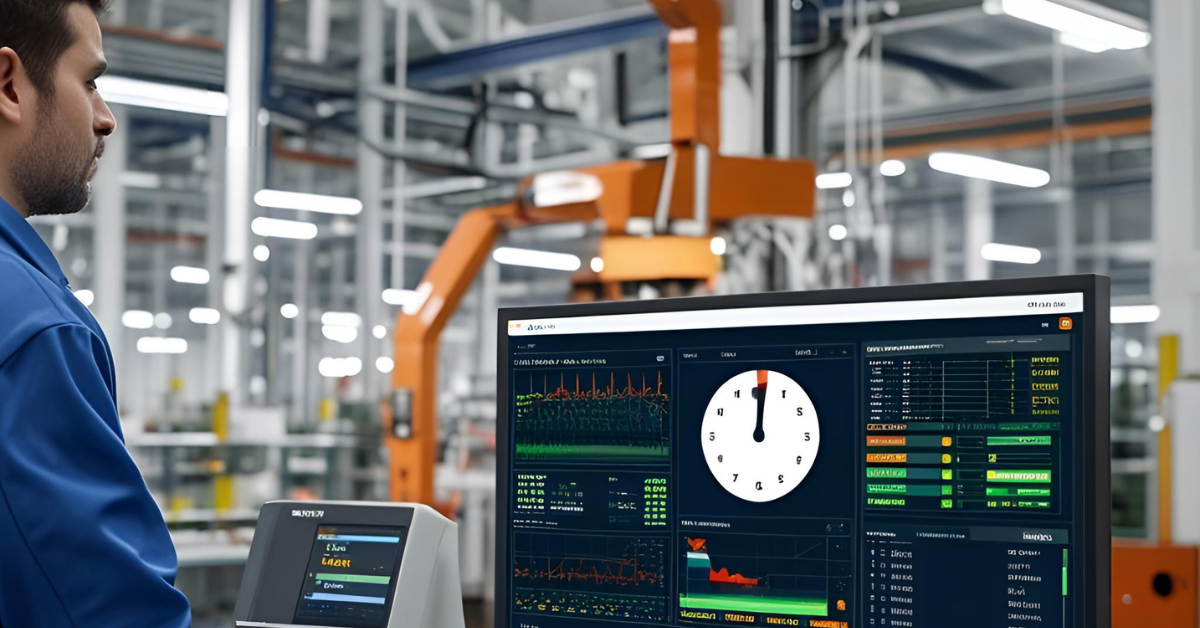
Overview: This project establishes a robust and real-time monitoring system for critical industrial conditions within a factory setting. It focuses on ensuring worker safety and regulatory compliance by continuously tracking parameters like the presence of hazardous gas leaks, elevated humidity levels, and abnormal temperature fluctuations. The system leverages a network of strategically placed sensors, connected to a central Raspberry Pi unit. This Raspberry Pi acts as the data aggregation and processing hub. The collected sensor data is then transmitted efficiently and reliably using the MQTT protocol to the ThingSpeak cloud platform. ThingSpeak provides powerful visualization tools, allowing factory personnel to monitor conditions remotely via a dashboard. Crucially, the system is designed to generate immediate alerts when unsafe conditions are detected, enabling swift responses to potential hazards. This proactive approach helps prevent accidents, ensure a safe working environment, and maintain adherence to industrial safety standards.
Details:
- Central Processing Unit: A Raspberry Pi (e.g., Raspberry Pi 4 or 3B+ for processing power and reliable network connectivity) is used to collect data from sensors and publish it to ThingSpeak.
- Sensor Integration:
- DHT22 Temperature and Humidity Sensor: This sensor provides accurate readings of both temperature and humidity, crucial for maintaining a comfortable and safe working environment and preventing damage to sensitive equipment or materials.
- MQ2 Gas Sensor: This sensor detects a wide range of combustible gases, including LPG, propane, methane, smoke, and alcohol. It's vital for detecting potential gas leaks, which can pose serious safety risks.
- Additional Sensors (Optional but Highly Recommended): Depending on the specific factory environment and potential hazards, additional sensors could be included:
- MQ7 Carbon Monoxide (CO) Sensor: For detecting this odorless, poisonous gas.
- MQ135 Air Quality Sensor: For detecting a broader range of air pollutants, including ammonia, nitrogen oxides, benzene, and alcohol.
- Flame Sensor: For detecting open flames, crucial in environments with flammable materials.
- Pressure Sensor: To monitor pressure levels in specific areas or equipment.
- Data Communication (MQTT):
- MQTT Protocol: The Raspberry Pi acts as an MQTT client, publishing sensor data to ThingSpeak. MQTT is a lightweight, publish-subscribe messaging protocol ideal for IoT applications with limited bandwidth.
- ThingSpeak as MQTT Broker: ThingSpeak acts as the MQTT broker, receiving and storing the sensor data.
- Cloud Platform and Visualization (ThingSpeak):
- ThingSpeak Channels: The sensor data is published to ThingSpeak channels, where it can be visualized in real-time using charts, gauges, and other widgets.
- Data Analysis: ThingSpeak provides basic data analysis tools, allowing users to identify trends and patterns in the environmental data.
- Alerting System (ThingSpeak React): ThingSpeak "React" apps can be configured to trigger alerts (e.g., email notifications) when sensor readings exceed predefined thresholds (e.g., high gas concentration, excessive temperature).
- Alert System:
- Visual and Audible Alarms: In addition to ThingSpeak alerts, the system can include local visual (e.g., flashing lights) and audible alarms (e.g., sirens) within the factory for immediate notification of unsafe conditions.
- SMS Alerts (Optional): Integration with a service like Twilio can enable SMS alerts to be sent to designated personnel for critical events.
Step-by-Step Procedure:
- Install Sensors (DHT22, MQ2, and others) in the factory environment: Strategically place sensors throughout the factory to ensure comprehensive coverage. Consider factors like potential leak sources, areas with high human traffic, and locations with sensitive equipment.
- Connect sensors to Raspberry Pi GPIO: Wire the sensors to the appropriate GPIO pins on the Raspberry Pi. Ensure proper power supply and signal connections.
- Program MQTT client to send data to ThingSpeak: Write a Python script to read sensor data, format it into MQTT messages, and publish it to the designated ThingSpeak channel. Use the ThingSpeak MQTT API credentials.
- Set thresholds and alert conditions in code: Within the Python script or using ThingSpeak "React" apps, define thresholds for each sensor (e.g., maximum allowable gas concentration, temperature range). Configure the system to trigger alerts when these thresholds are exceeded.
- Create dashboard and alert system: Create a ThingSpeak dashboard to visualize the sensor data in real-time. Configure email alerts or integrate with other alerting mechanisms (e.g., SMS via Twilio, local alarms).
Key Technologies Used:
- Raspberry Pi: A low-cost, versatile computer used as the central data collection and processing unit.
- DHT22: A temperature and humidity sensor.
- MQ2: A gas sensor that detects a range of combustible gases.
- MQTT: A lightweight messaging protocol for IoT applications.
- ThingSpeak: An IoT analytics platform for data visualization and storage.
- Additional Sensors (MQ7, MQ135, Flame Sensor, etc.): For detecting specific hazards in the factory environment.
Benefits:
- Improved worker safety: Real-time monitoring and alerts enable rapid responses to unsafe conditions, preventing accidents and protecting workers.
- Real-time alerts: Immediate notification of hazards allows for timely intervention, minimizing potential damage and ensuring a safe working environment.
- Industrial compliance with analytics: The system helps factories comply with safety regulations by providing a detailed record of environmental conditions and generating reports for auditing purposes.
- Process Optimization: Monitoring temperature and humidity can help optimize industrial processes and prevent damage to sensitive materials or equipment.
- Reduced Downtime: Early detection of potential problems can prevent equipment failures and minimize downtime.
- Remote Monitoring: Factory personnel can monitor conditions from anywhere with an internet connection, improving efficiency and responsiveness.
- Data-Driven Insights: The system provides valuable data for analyzing trends and identifying potential areas for improvement in factory safety and efficiency.
Project 4: MQTT-Based Factory Environment Monitoring Codes:
🔗 View Project Code on GitHub🧰 Hardware Requirements
|
Component |
Purpose |
|
Raspberry
Pi (any model with WiFi) |
Central
controller |
|
DHT22 |
Temperature
& Humidity |
|
MQ2 |
Gas/smoke
detection |
|
Buzzer
(optional) |
Alert
feedback |
|
Wi-Fi |
For MQTT
& ThingSpeak upload |
⚙️ Software Requirements
· Python 3
· paho-mqtt
· Adafruit_DHT
· ThingSpeak MQTT credentials
📦 Install Required Libraries
Run this on your Pi:
bashCopyEdit
sudo apt-get updatesudo pip3 install paho-mqtt Adafruit_DHT🔐 ThingSpeak MQTT Credentials Setup
Create a ThingSpeak account and a new channel.
· Go to Channel Settings → copy your Write API Key
· MQTT Broker: mqtt3.thingspeak.com
· MQTT Port: 1883
· MQTT Username: your API key
· Client ID: uniqueClientID (any string)
· Topic format: channels/<channelID>/publish/<writeAPIKey>
📊 ThingSpeak Field Mapping
|
Field |
Data |
|
field1 |
Temperature
(°C) |
|
field2 |
Humidity
(%) |
|
field3 |
Gas
Detected (0/1) |
🧾 Optional Enhancements
· Add email or SMS alerts with Twilio or SMTP
· Deploy Grafana for richer analytics via InfluxDB
· Build an industrial dashboard on a local screen using Tkinter or PyQT
· Integrate with Home Assistant or Node-RED for smart triggers
5. ⚡ Transformer Health Monitoring Using IoT
Overview: This project provides a critical solution for ensuring the reliability and longevity of electrical transformers, which are vital components of power grids. It establishes a comprehensive, real-time health monitoring system utilizing the capabilities of the Internet of Things (IoT). The core of the system is an ESP32 microcontroller, a powerful and versatile board known for its Wi-Fi connectivity. Integrated with the ESP32 are essential sensors: the INA219 current/voltage sensor for precise measurement of electrical parameters (voltage, current, and power) and the DS18B20 temperature sensor for continuous monitoring of key temperature points within the transformer (e.g., winding temperature, oil temperature). All collected operational data is securely transmitted to the ThingSpeak cloud platform for robust data storage, analysis, and intuitive visualization, enabling "cloud diagnostics." Crucially, the system incorporates relays to provide an automated fault control mechanism. When predefined critical thresholds for temperature or electrical parameters are breached, the system can automatically trigger these relays to isolate the transformer or activate cooling systems, thereby preventing severe damage, costly outages, and ensuring uninterrupted power supply.
Details:
- Central Processing Unit: The ESP32 microcontroller is chosen for its integrated Wi-Fi capabilities, sufficient processing power, and multiple GPIO pins, making it ideal for continuous data acquisition and cloud communication. Its low power consumption can also be an advantage for remote deployments if solar or limited power sources are available.
- Sensor Integration:
- DS18B20 Temperature Sensor: Multiple DS18B20 sensors can be strategically placed to monitor various critical temperature points within the transformer, such as:
- Transformer Oil Temperature: A primary indicator of internal heat generation.
- Winding Temperature: Directly reflects the thermal stress on the transformer's insulation.
- Ambient Temperature: Provides a baseline for environmental conditions affecting the transformer. These sensors communicate over a one-wire bus, allowing multiple sensors to be connected to a single ESP32 GPIO pin, simplifying wiring.
- INA219 Current/Voltage/Power Sensor: This high-side current shunt monitor with an I2C interface is excellent for precisely measuring:
- Bus Voltage: The voltage across the transformer's terminals.
- Shunt Voltage: Voltage drop across a shunt resistor, from which current is calculated.
- Current: The load current drawn from the transformer.
- Power: Calculated from voltage and current. Monitoring these electrical parameters helps in detecting overloads, short circuits, or anomalous power consumption patterns that could indicate internal faults.
- DS18B20 Temperature Sensor: Multiple DS18B20 sensors can be strategically placed to monitor various critical temperature points within the transformer, such as:
- Cloud Platform and Data Visualization (ThingSpeak):
- Data Transmission: The ESP32 collects sensor data and sends it to the ThingSpeak cloud platform using its built-in Wi-Fi. Data is typically published as HTTP POST requests or via the MQTT protocol (which ThingSpeak supports).
- Cloud Diagnostics: ThingSpeak acts as a central repository for all the transformer's operational data. It provides:
- Real-time Dashboards: Visualizations (charts, gauges, numeric displays) of temperature, voltage, current, and power, allowing operators to monitor the transformer's health at a glance.
- Historical Data: Storage of past sensor readings, enabling trend analysis and identification of gradual degradation.
- Data Analytics: ThingSpeak can perform basic analytics and calculations on the incoming data.
- Automated Fault Control (Relays):
- Relay Integration: Industrial-grade relays are connected to the ESP32's GPIO pins. These relays act as electrical switches to control external high-power devices.
- Fault Response Logic: The ESP32's firmware is programmed with logic to:
- Detect Threshold Breaches: Continuously compare sensor readings against predefined safe operating thresholds (e.g., maximum oil temperature, current overload limits).
- Trigger Relays: If a critical threshold is breached, the ESP32 activates specific relays. These relays can be configured to:
- Trip Circuit Breakers: Isolate the transformer from the power grid to prevent further damage.
- Activate Cooling Fans/Pumps: Turn on forced cooling systems if the temperature rises beyond acceptable limits.
- Trigger Alarms: Activate local audible or visual alarms (e.g., sirens, warning lights) at the substation.
- Send Remote Alerts: In addition to ThingSpeak alerts, the ESP32 can be programmed to send SMS alerts via a service like Twilio (as in other projects) or email notifications to maintenance personnel for immediate attention.
Step-by-Step Procedure:
- Connect INA219 and DS18B20 to ESP32:
- DS18B20: Connect the data pin of the DS18B20 to a digital GPIO pin on the ESP32. Ensure a 4.7kΩ pull-up resistor is used between the data pin and VCC.
- INA219: Connect the INA219's SDA and SCL pins to the ESP32's I2C pins (typically GPIO21 and GPIO22).
- Relays: Connect the control pins of the relays to other available digital GPIO pins on the ESP32. Ensure proper current limiting and isolation for the relay module.
- Program ESP32 to send data to ThingSpeak:
- Use the Arduino IDE or PlatformIO for ESP32 development.
- Include necessary libraries for DS18B20 (e.g., OneWire, DallasTemperature), INA219 (e.g., Adafruit_INA219), and ThingSpeak communication (e.g., WiFiClient, ThingSpeak).
- Write code to initialize sensors, read data, connect to Wi-Fi, and publish sensor readings to your ThingSpeak channel's fields periodically.
- Define thresholds and set up alert triggers:
- Within your ESP32 code, define critical temperature and current/voltage thresholds.
- Implement if conditions to check if sensor readings exceed these thresholds.
- On ThingSpeak, set up "ThingSpeak React" apps to send email alerts or trigger webhooks when specific channel field values cross defined limits.
- Control relay switches to prevent transformer damage:
- In the ESP32 code, upon detection of a critical threshold breach, set the corresponding GPIO pin connected to the relay to HIGH or LOW to activate or deactivate the relay, thereby controlling the external circuit (e.g., tripping a circuit breaker or activating a cooling fan).
- Visualize live data on ThingSpeak:
- Log into your ThingSpeak account, create a new channel, and add fields corresponding to each sensor (e.g., "Oil Temp," "Winding Temp," "Current," "Voltage," "Power").
- Configure charts, gauges, and numeric displays for each field to visualize the real-time data streaming from the ESP32.
Key Technologies Used:
- ESP32: A powerful microcontroller with integrated Wi-Fi and Bluetooth, serving as the core of the monitoring system.
- INA219 Current/Voltage Sensor: Provides precise measurements of electrical parameters to detect overloads and anomalies.
- DS18B20 Temperature Sensor: Robust digital temperature sensor for monitoring critical temperature points.
- ThingSpeak: Cloud IoT platform for data collection, visualization, and basic analytics, enabling remote cloud diagnostics.
- Relays: Electromechanical switches controlled by the ESP32 to enact automated responses (e.g., circuit breaker tripping, cooling fan activation) to prevent transformer damage.
Benefits:
- Preventive Maintenance: Shifts from reactive (breakdown) maintenance to predictive maintenance. Early detection of anomalies allows for scheduled repairs, preventing catastrophic failures and extending the transformer's lifespan.
- Cloud Data Visualization: Provides operators and maintenance teams with real-time, remote access to critical transformer health data via a web dashboard, enhancing monitoring capabilities and decision-making.
- Automated Fault Response: The integration of relays for automated control significantly reduces response time to critical events, minimizing damage and ensuring rapid isolation of faulty components, thus improving grid reliability.
- Reduced Downtime and Costs: By preventing major failures and enabling proactive maintenance, the system drastically reduces unplanned outages, repair costs, and associated economic losses.
- Improved Safety: Early detection of issues like overheating or overcurrent conditions mitigates risks to personnel and equipment.
- Optimized Performance: Continuous monitoring helps in understanding the transformer's operational characteristics under various load conditions, leading to better asset utilization.
Project 5: Transformer Health Monitoring Using IoT Codes:
🔗 View Project Code on GitHub🧠 Concept Recap
The ESP32 gathers temperature (DS18B20) and power metrics (INA219), ships them to ThingSpeak, and toggles relays when thresholds get dangerous (like overheating or overcurrent). This means real-time monitoring + self-protective response.
🧰 Wiring Summary
· DS18B20 →
o VCC to 3.3V
o GND to GND
o Data to GPIO 14 + 4.7kΩ pull-up
· INA219 → (I2C)
o VCC to 3.3V
o GND to GND
o SDA to GPIO 21
o SCL to GPIO 22
· Relay →
o IN to GPIO 15
o VCC & GND to 5V logic level converter or directly to ESP32 (if module supports 3.3V)
📦 Libraries Required (Arduino IDE)
Install these:
· Adafruit INA219
· OneWire
· DallasTemperature
· WiFi.h
📊 ThingSpeak Field Mapping
|
Field |
Data |
|
Field1 |
Temperature
(°C) |
|
Field2 |
Voltage
(V) |
|
Field3 |
Current (A) |
🚨 Custom Threshold Ideas
· Temp > 75°C → Overheat protection
· Current > 5A → Overload protection
· Voltage drop < 200V → Under-voltage trip
You can tweak the thresholds per your transformer’s rating.
🧠 Bonus Ideas
· Use Blynk or Telegram for mobile alerts
· Add OLED display for local readings
· Push data to Firebase for smart analytics
6. 👵 Elderly Fall Detection System
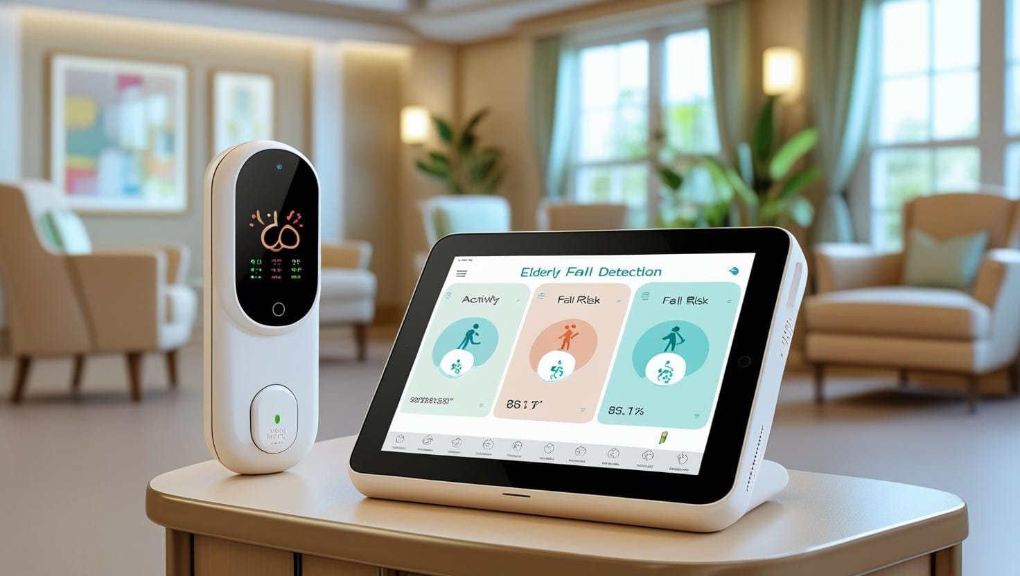
Overview: This project presents a vital and unobtrusive wearable solution designed to enhance the safety and independence of elderly individuals, particularly those living alone or at risk of falls. The core of the system is the MPU6050, a 6-axis Inertial Measurement Unit (IMU), which combines an accelerometer and gyroscope to accurately detect sudden and specific patterns of movement indicative of a fall. This sensor is typically worn by the elderly person (e.g., as a wristband, pendant, or integrated into a belt). When a fall is detected, the system immediately springs into action: an integrated GPS module acquires the user's precise geographical coordinates. This location data, along with an emergency message, is then sent as an SMS alert to pre-registered caregivers or emergency contacts via a GSM module. This direct cellular communication ensures alerts are sent even without Wi-Fi or Bluetooth connectivity to a smartphone. An Arduino microcontroller acts as the central processing unit, managing sensor readings and communication. Additionally, a piezo buzzer is included for local audible alerts, confirming to the user that a fall has been detected and help is being dispatched. This comprehensive system provides peace of mind for both the elderly user and their families by ensuring rapid response in critical situations.
Details:
· Central Processing Unit: An Arduino board (e.g., Arduino Nano, Uno, or a smaller Pro Mini for wearability) serves as the brain of the system. It's chosen for its ease of programming, low power consumption, and suitability for embedded applications.
· Fall Detection Sensor:
- MPU6050 (6-axis Accelerometer & Gyroscope): This IMU sensor is crucial for detecting falls.
- Accelerometer: Measures linear acceleration along X, Y, and Z axes. A sudden change in acceleration (e.g., free fall followed by an impact) is a key indicator of a fall.
- Gyroscope: Measures angular velocity. Abnormal rotational movements can also be indicative of a fall.
- Fall Detection Algorithm: The Arduino code implements a sophisticated algorithm that analyzes the raw data from the MPU6050. This algorithm differentiates between normal activities (like sitting, standing, walking) and a genuine fall, minimizing false positives. Common techniques involve:
- Thresholding: Detecting if the total acceleration (magnitude of the vector sum of X, Y, Z accelerations) drops below a certain threshold (indicating free fall) and then exceeds another threshold (indicating impact).
- Angle Change: Monitoring the change in orientation (pitch and roll angles derived from accelerometer/gyroscope data) to detect a significant change in body posture.
· Location Tracking:
- GPS Module (e.g., NEO-6M, SIM28ML): This module acquires the user's real-time latitude and longitude coordinates. It connects to the Arduino via a serial interface (UART). The GPS data is parsed by the Arduino to extract the current location.
· Communication for Alerts:
- GSM Module (e.g., SIM900A, SIM800L): This module provides cellular connectivity, allowing the system to send SMS messages. It communicates with the Arduino via serial communication. It requires a valid SIM card with an active plan.
- SMS Alert Mechanism: Upon fall detection, the Arduino code formats an SMS message. This message typically includes:
- A clear notification: "Emergency: Possible fall detected!"
- The user's GPS coordinates: "Location: Latitude: [Lat], Longitude: [Long]"
- A direct link to a mapping service: "View on map: http://maps.google.com/maps?q=[Lat],[Long]"
- Optionally, a timestamp.
· Local Confirmation/Alert:
- Piezo Buzzer: A small buzzer connected to an Arduino digital pin. When a fall is detected and the SMS alert is being sent, the buzzer emits a short, audible sound. This serves as a confirmation to the elderly person that the system has registered the event and help is being dispatched. It can also help attract immediate attention from anyone nearby.
· Wearability:
- The entire system (Arduino, sensors, modules, and battery) is designed to be compact and lightweight, enclosed in a durable, non-obtrusive casing that can be comfortably worn as a wristband, pendant, or clipped onto clothing. Battery life optimization is crucial for continuous use.
Step-by-Step Procedure:
- Interface MPU6050 with Arduino:
- Connect the MPU6050 to the Arduino using the I2C communication protocol (SDA and SCL pins).
- Install the necessary Arduino libraries for the MPU6050 (e.g.,
Adafruit_MPU6050orWire).
- Connect GPS and GSM modules:
- Connect the GPS module's TX/RX pins to dedicated Arduino software serial pins or hardware serial if available.
- Connect the GSM module's TX/RX pins to other Arduino software serial pins.
- Ensure the GSM module has a valid SIM card inserted and is powered correctly (GSM modules often require a higher current supply than the Arduino can provide directly, so an external power supply might be needed).
- Write Arduino code to detect sudden movements and falls:
- Program the Arduino to continuously read accelerometer and gyroscope data from the MPU6050.
- Implement a fall detection algorithm. This typically involves:
- Calculating the magnitude of the accelerometer vector.
- Checking for a sudden drop in acceleration (simulating free fall).
- Checking for a subsequent impact (sudden peak in acceleration).
- Analyzing angular velocity changes to refine fall detection.
- Introducing a timer to avoid false positives (e.g., if acceleration returns to normal quickly, it's not a fall).
- On fall detection, send SMS with location:
- When the fall detection algorithm confirms a fall, use the GSM module to acquire the current GPS coordinates.
- Construct the SMS message including the alert, coordinates, and Google Maps link.
- Use the GSM module's AT commands (sent via serial communication from Arduino) to send the SMS to the pre-configured emergency contact numbers.
- Add piezo buzzer for local alerts:
- Connect a piezo buzzer to a digital output pin on the Arduino.
- In the fall detection logic, activate the buzzer for a short duration to provide immediate audible feedback to the user.
Key Technologies Used:
- MPU6050: A 6-axis IMU (accelerometer + gyroscope) for detecting falls and sudden movements.
- GPS Module: Provides precise geographical coordinates for the user's location.
- GSM Module: Enables cellular communication to send SMS alerts to caregivers, independent of Wi-Fi.
- Arduino: The microcontroller platform used for processing sensor data and managing communication.
- Piezo Buzzer: Provides local audible feedback to the user upon fall detection.
Benefits:
- Emergency Alerts: Provides immediate, automated SMS alerts to caregivers or emergency services, significantly reducing response time in critical situations.
- Location Tracking: Inclusion of GPS ensures that caregivers receive the precise location of the fallen individual, enabling faster assistance, especially if the fall occurs outdoors or in an unfamiliar indoor setting.
- Discreet and Wearable: The system is designed to be compact and easily wearable, minimizing intrusion into the user's daily life while providing continuous monitoring.
- Enhanced Safety and Peace of Mind: Offers a crucial safety net for elderly individuals living independently and provides reassurance for their families.
- Reduced "Lie Time": A key benefit is minimizing the time an individual lies on the ground after a fall, which significantly impacts recovery and reduces complications.
Project: 6. 👵 Elderly Fall Detection System Codes:
🔗 View Project Code on GitHub⚙️ Hardware Breakdown
|
Component |
Role |
|
Arduino Uno |
Main
controller |
|
MPU6050 |
Detects
motion & sudden falls |
|
GPS Module |
Provides
location coordinates |
|
GSM Module |
Sends
SMS alerts |
|
Piezo Buzzer |
Local
audible alert on fall |
🔌 Wiring Summary
· MPU6050 (I2C)
o VCC to 5V
o GND to GND
o SDA to A4
o SCL to A5
· GPS Module
o VCC to 5V
o GND to GND
o TX to Arduino RX (Pin 0)
o RX to Arduino TX (Pin 1)
· GSM Module (SIM800L or similar)
o VCC to external 4V power supply (do NOT power from Arduino 5V)
o GND common with Arduino
o TX to Arduino RX (Pin 2)
o RX to Arduino TX (Pin 3)
· Piezo Buzzer
o Positive to digital pin 8
o Negative to GND
📚 Libraries Needed
· Wire.h (for MPU6050)
· MPU6050.h or MPU6050_light (lightweight MPU library)
· TinyGPS++.h (for GPS parsing)
· SoftwareSerial.h (for GSM communication)
🚦 How It Works
· MPU6050 detects sudden high acceleration magnitude beyond the threshold, signaling a potential fall.
· GPS module continuously updates location.
· GSM module sends SMS alert with Google Maps link to caregiver.
· Buzzer sounds locally to alert nearby people.
⚠️ Important
· Calibrate the FALL_THRESHOLD to minimize false positives/negatives.
· Ensure GSM module power supply is stable — it’s the weakest link in many setups.
· Test GPS lock outdoors for reliable coordinates.
· Replace "+1234567890" with the actual caregiver phone number.

🚀 Ready to turn your IoT knowledge into a career-ready superpower?
At Huebits, we don’t just teach IoT—we train you to build, deploy, and dominate the industry with hands-on hardware experience, real-world projects, and cloud-integrated systems like AWS IoT, Grafana, and MQTT.
🛠️ Whether you're a student, engineer, or tech enthusiast, our Industry-Ready IoT Program is designed to make you future-proof. Learn edge computing, embedded systems, and AI-integrated automation—all in one power-packed journey.
🎓 Next Cohort starts soon!
🔗 Join Now to reserve your spot and take the first step into India’s ₹1.3 trillion IoT future.
7. 📶 IoT-Based Smart Feeder Monitoring System
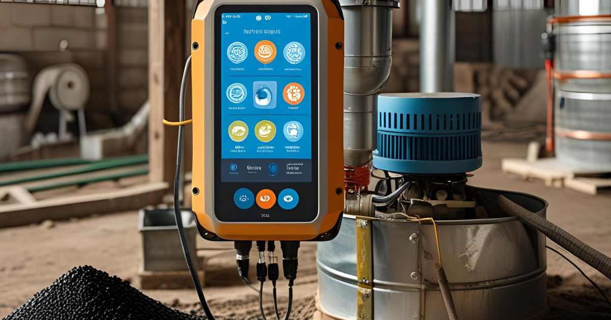
Overview: This project introduces an intelligent, IoT-based solution for real-time monitoring of electrical power feeders, which are crucial segments of the electricity distribution network. Its primary objective is to track energy flow, detect anomalies, and provide immediate alerts to ensure grid stability and prevent power outages. The system utilizes PZEM-004T sensors, which are designed to precisely measure key electrical parameters such as voltage, current, power consumption (active power), and energy (kilowatt-hours). An ESP32 microcontroller acts as the central data acquisition unit, collecting readings from these sensors. The gathered data is then uploaded to the ThingSpeak cloud platform for robust data storage, analysis, and interactive visualization. This allows utility operators or facility managers to remotely monitor the health and performance of their feeders. Crucially, in the event of detected faults, overloads, or abnormal readings, the system leverages a GSM module to send instant SMS notifications to relevant personnel, enabling rapid response and proactive maintenance. This comprehensive monitoring system significantly enhances grid performance tracking, reliability, and allows for data-driven fault diagnosis.
Details:
· Central Processing Unit: The ESP32 microcontroller is an ideal choice due to its integrated Wi-Fi (for ThingSpeak communication), sufficient processing power, and multiple serial interfaces which are often required for communicating with modules like the PZEM-004T and GSM.
· Energy Parameter Measurement:
- PZEM-004T Sensor: This low-cost, high-precision AC power monitor module is central to the project. It connects in series with the power feeder line and communicates with the ESP32 via a serial interface (UART). It provides readings for:
- Voltage (V): The actual voltage present in the feeder.
- Current (A): The current flowing through the feeder.
- Active Power (W): The real power consumed by the load.
- Energy (kWh): Accumulates the total energy consumed over time, essential for billing and load analysis.
- Frequency (Hz): In some versions, frequency measurement is also available.
- Power Factor: Indicates the efficiency of power utilization.
- Placement: The PZEM-004T (or multiple units) would be installed at critical points along the power feeder, often in distribution boxes or near major load points.
· Data Communication (Cloud & SMS):
- ThingSpeak Integration: The ESP32 collects the data from the PZEM-004T and periodically publishes it to a designated ThingSpeak channel using its built-in Wi-Fi. This allows for:
- Cloud Storage: Long-term storage of feeder data for historical analysis.
- Real-time Visualization: Creation of dashboards with charts, gauges, and numerical displays for immediate monitoring of voltage, current, power, and energy.
- Basic Analytics: ThingSpeak can perform simple calculations and event triggers.
- GSM Module (e.g., SIM800L, SIM900A): This module provides cellular communication capability. It connects to the ESP32 via a serial interface. It requires a valid SIM card with an active plan.
- SMS Fault Notifications: The ESP32 is programmed to constantly check the readings from the PZEM-004T against predefined thresholds. If a fault condition is detected (e.g., overcurrent, undervoltage, power fluctuation outside normal range, unusual energy consumption pattern), the GSM module is activated to send an SMS alert to pre-configured numbers of maintenance personnel or utility operators. The SMS typically includes the type of fault, the feeder ID, and the current readings.
· Fault Detection Logic:
- The ESP32's firmware contains the intelligence to analyze the incoming data. This logic involves:
- Threshold Monitoring: Comparing real-time voltage, current, and power readings against upper and lower safe operating limits.
- Pattern Recognition (Basic): Detecting sudden spikes or drops in parameters that deviate significantly from historical norms.
- Fault Identification: Categorizing the detected anomaly (e.g., overcurrent, undervoltage, no power/feeder trip).
Step-by-Step Procedure:
- Wire PZEM-004T to measure energy parameters:
- Connect the PZEM-004T module to the power feeder according to its wiring diagram (typically involves connecting the current transformer to the phase wire and voltage terminals to the live and neutral).
- Connect the PZEM-004T's TX/RX pins to dedicated UART pins on the ESP32.
- Use ESP32 to collect data and push to ThingSpeak:
- Program the ESP32 (using Arduino IDE or PlatformIO) to communicate with the PZEM-004T using its serial protocol.
- Read voltage, current, power, and energy data.
- Connect the ESP32 to a Wi-Fi network.
- Use the ThingSpeak library or direct HTTP/MQTT calls to publish the collected data to your designated ThingSpeak channel fields.
- Set up GSM module for SMS alerts:
- Connect the GSM module's TX/RX pins to another set of serial pins on the ESP32.
- Insert a functional SIM card into the GSM module and ensure it's powered correctly (often requiring an external power supply).
- Program the ESP32 to send AT commands to the GSM module for sending SMS messages.
- Configure dashboard for real-time analytics:
- Log into your ThingSpeak account and create a channel with fields for voltage, current, power, and energy.
- Create various visualizations (line charts for trends, gauges for current values, numeric displays).
- (Optional) Use ThingSpeak's MATLAB analysis or custom "React" apps for more advanced analytics or triggering additional actions.
- Add control logic for fault detection:
- Within the ESP32 code, implement conditional statements (if-else) to monitor sensor readings against predefined critical thresholds (e.g., if current > X amps, if voltage < Y volts).
- If a fault is detected, trigger the GSM module to send an SMS alert.
- Consider implementing a debouncing or averaging mechanism for readings to prevent false alarms.
Key Technologies Used:
- ESP32: A versatile microcontroller with built-in Wi-Fi, suitable for data collection and communication.
- PZEM-004T: An AC energy monitor module for measuring voltage, current, power, and energy in power feeders.
- GSM Module: Provides cellular connectivity for sending SMS alerts, ensuring communication even without Wi-Fi.
- ThingSpeak: Cloud IoT platform for data storage, real-time visualization, and basic analytics.
Benefits:
- Grid Performance Tracking: Provides continuous, real-time insights into the operational health and load conditions of power feeders, enabling utility companies to monitor grid performance effectively.
- Real-time SMS Alerts: Immediate notification of fault conditions (e.g., overloads, voltage drops, power outages) via SMS ensures rapid response times, minimizing service disruptions.
- Cloud-Based Analytics: Historical data stored on ThingSpeak enables comprehensive analysis of energy consumption patterns, fault occurrences, and feeder performance trends, aiding in predictive maintenance and system optimization.
- Preventive Maintenance: Early detection of anomalies allows for proactive intervention, preventing major equipment failures and costly downtime.
- Reduced Revenue Loss: By quickly identifying and addressing faults, utilities can minimize energy theft and non-technical losses.
- Improved Reliability: Contributes to a more stable and reliable power distribution network by enabling quicker fault isolation and restoration.
Project: 7. IoT-Based Smart Feeder Monitoring System Codes:
🔗 View Project Code on GitHub⚙️ Hardware Setup Summary
|
Component |
Role |
|
ESP32 |
Main
controller |
|
PZEM-004T |
Measures
voltage, current, power etc. |
|
GSM Module |
Sends
SMS alerts |
🔌 Wiring Essentials
· PZEM-004T:
o RX to ESP32 TX (GPIO 17)
o TX to ESP32 RX (GPIO 16)
o Power supply per specs (5V or 3.3V depending on module)
· GSM Module (SIM800/900):
o RX to ESP32 TX (GPIO 4)
o TX to ESP32 RX (GPIO 2)
o External power supply (avoid powering from ESP32)
📚 Libraries Required
· HardwareSerial (ESP32 has multiple hardware serial ports)
· PZEM004T library (for sensor communication)
· WiFi.h (for ThingSpeak connectivity)
· HTTPClient.h (for POST requests to ThingSpeak)
🎯 How This Rolls
· ESP32 reads voltage, current, power, and energy from PZEM-004T every 15 seconds.
· Data is pushed to ThingSpeak via HTTP GET request for cloud analytics.
· If voltage/current cross thresholds, GSM fires off SMS alert.
· Real-time monitoring with cloud dashboards + instant SMS fault notifications.
💡 Pro Tips
· Calibrate thresholds to fit your specific feeder specs and regional power norms.
· Ensure GSM module is on stable external power; weak power kills connectivity.
· Use a dedicated SIM with SMS enabled and balance.
· Secure your ThingSpeak API keys and WiFi credentials — avoid hardcoding in production.
· Use TLS/SSL if possible for HTTPS, though ESP32 HTTPClient supports it with some setup.
8. 🔌 Remote Transformer Health Monitoring Using IOT
Overview: This project represents an enhanced and more sophisticated iteration of transformer health monitoring, moving beyond basic parameter tracking to implement multi-sensor fusion and advanced cloud visualization for comprehensive diagnostics. It focuses on providing a holistic view of the transformer's operational status and predicting potential failures with greater accuracy. The system integrates an ESP32 microcontroller as the primary data acquisition and processing unit, connected to a wider array of sensors than a basic system. These include INA219 current/voltage sensors for electrical load analysis, DS18B20 temperature sensors for precise thermal mapping (oil, winding, ambient), and crucially, ultrasonic sensors (HC-SR04) for monitoring physical parameters like oil level or bushing degradation (by detecting partial discharge sounds, or even changes in cooling fan efficiency). All this rich sensor data is meticulously collected and securely transmitted in real-time to the ThingSpeak cloud platform. ThingSpeak provides not just basic charts but powerful, customizable dashboards for visualizing diverse data streams, enabling deeper insights into transformer health. A key enhancement is the implementation of relay-based automation, which allows the system to enact proactive responses to detected anomalies, such as activating cooling systems or initiating protective shutdowns. The architecture is designed to be scalable and modular, allowing for easy expansion to monitor multiple transformers across a vast network with centralized management.
Details:
- Central Processing Unit: The ESP32 microcontroller is chosen for its powerful dual-core processor, ample memory, integrated Wi-Fi, and multiple communication interfaces (I2C, One-Wire, UART for ultrasonic sensors). Its capabilities enable it to handle simultaneous sensor readings, complex data processing (for multi-sensor fusion), and robust cloud communication.
- Multi-Sensor Fusion for Comprehensive Diagnostics:
- INA219 Current/Voltage Sensor: Measures critical electrical parameters:
- Voltage: Detects under/overvoltage conditions, crucial for grid stability.
- Current: Monitors load, detects overcurrents indicating potential short circuits or excessive demand.
- Power (Watts) & Energy (kWh): Provides insights into load consumption and efficiency.
- Purpose: Helps diagnose electrical faults, overloads, and track energy throughput.
- DS18B20 Temperature Sensors (Multiple): Deployed strategically for granular thermal monitoring:
- Transformer Oil Temperature: Indicates the overall thermal stress on the insulation and cooling system effectiveness.
- Winding Temperature: Directly reflects the health of insulation, crucial for preventing thermal breakdown.
- Ambient Temperature: Provides context for other temperature readings and helps assess cooling needs.
- Purpose: Essential for detecting overheating, monitoring cooling system efficiency, and predicting insulation degradation.
- HC-SR04 Ultrasonic Sensor (or similar): While typically used for distance, its application here is enhanced:
- Oil Level Monitoring: Mounted above the oil level, it can continuously measure the distance to the oil surface, providing real-time oil level indications. Low oil levels can lead to overheating and reduced insulation.
- Bushing/Insulator Degradation (advanced concept): In more advanced applications, very sensitive ultrasonic transducers can potentially be used to detect partial discharge (PD) activity, which emits ultrasonic waves as an early indicator of insulation breakdown in bushings or windings. This requires specialized knowledge and highly sensitive sensors.
- Cooling Fan Efficiency Monitoring: Mounted near cooling fans, it could potentially detect changes in airflow patterns or the presence of debris by analyzing sound reflections.
- Purpose: Adds a physical dimension to monitoring, detecting issues like low oil, or potentially early signs of insulation failure.
- INA219 Current/Voltage Sensor: Measures critical electrical parameters:
- Cloud Visualization and Analytics (ThingSpeak):
- Real-time Data Transmission: The ESP32 collects all sensor data and transmits it wirelessly (via Wi-Fi) to ThingSpeak using HTTP POST requests or MQTT.
- Comprehensive Dashboards: ThingSpeak allows for the creation of rich, customizable dashboards. This enhanced version would feature multiple charts, gauges, and widgets displaying all sensor data simultaneously, providing a holistic view of the transformer's health.
- Historical Data & Trend Analysis: All data is logged, enabling operators to analyze long-term trends, identify cyclical patterns, and detect gradual degradation over time, which is crucial for predictive maintenance.
- Mathematical Operations & Alerts: ThingSpeak's built-in functions (e.g., MATLAB analysis within ThingSpeak) can be used to perform calculations (e.g., calculate power factor, rate of temperature rise) and trigger sophisticated alerts (e.g., email, push notifications, webhooks) based on complex conditions involving multiple sensor readings.
- Automated Fault Response (Relays):
- Relay Modules: Industrial-grade relays are connected to the ESP32's GPIO pins, capable of switching high-power circuits.
- Intelligent Control Logic: The ESP32's firmware, based on the fused sensor data and sophisticated algorithms, will activate these relays for automated responses:
- Automatic Cooling Activation: If oil or winding temperature exceeds a safe threshold, relays can activate auxiliary cooling fans or pumps.
- Circuit Breaker Tripping: In severe overload or fault conditions (e.g., detected by INA219, or excessive oil temperature), relays can trigger associated circuit breakers to isolate the transformer, preventing catastrophic damage and cascading failures.
- Alarm Activation: Local audible alarms or visual beacons can be activated to alert nearby personnel.
- Scalable and Modular Architecture:
- Modular Design: Each transformer monitoring unit (ESP32 + sensors) can be designed as a standalone module.
- Scalability: New units can be easily added to monitor additional transformers. All units report to the same central ThingSpeak account (or a private cloud server), enabling a centralized monitoring dashboard for an entire fleet of transformers.
- Open-Source Technologies: The use of ESP32 and ThingSpeak fosters an open and adaptable system for future upgrades and integrations.
Step-by-Step Procedure:
- Connect INA219, DS18B20, and ultrasonic sensors to ESP32:
- INA219: Connect via I2C (SDA/SCL pins).
- DS18B20: Connect multiple sensors to a single GPIO pin using a 4.7kΩ pull-up resistor for the One-Wire protocol.
- HC-SR04: Connect Trigger and Echo pins to dedicated GPIOs.
- Relays: Connect control pins to other GPIOs (ensure appropriate driver circuits if needed).
- Code multi-sensor logic for fault diagnostics:
- Develop ESP32 firmware (using Arduino IDE/PlatformIO) to:
- Continuously read data from all sensors.
- Implement sensor fusion algorithms (e.g., combining temperature rate of change with current load to predict overheating).
- Define complex fault detection logic based on multiple conditions (e.g., "IF Oil Temp > T1 AND Current > I1 THEN Overload Alert").
- Implement data filtering and averaging to reduce noise.
- Develop ESP32 firmware (using Arduino IDE/PlatformIO) to:
- Send data to ThingSpeak in real-time:
- Configure Wi-Fi connectivity for the ESP32.
- Format collected and processed sensor data into suitable payloads (JSON is common).
- Publish data to specific fields within a ThingSpeak channel at regular intervals.
- Implement relay controls for fault automation:
- Within the ESP32 code's fault detection routines, program the corresponding GPIO pins to activate/deactivate relays when critical conditions are met. This could include switching on cooling fans, or sending a signal to a main circuit breaker.
- Visualize historical data and alerts:
- On ThingSpeak, create a comprehensive dashboard with multiple charts for each sensor, showing real-time and historical trends.
- Configure ThingSpeak "React" apps to trigger email/SMS alerts or webhooks when complex fault conditions are detected by the ESP32 or derived by ThingSpeak's internal analytics.
Key Technologies Used:
- ESP32: High-performance microcontroller with Wi-Fi, ideal for complex multi-sensor applications.
- INA219: Precision current, voltage, and power monitoring sensor.
- DS18B20: Robust digital temperature sensor for granular thermal mapping.
- HC-SR04 (or similar ultrasonic): For physical parameter monitoring like oil level, or advanced diagnostics like partial discharge detection.
- ThingSpeak: Cloud-based IoT platform for advanced data visualization, storage, and analytics, enabling remote diagnostics.
- Relays: Electromechanical switches for automated control and protective actions (e.g., activating cooling, tripping breakers).
Benefits:
- Comprehensive Diagnostics: Provides a much richer dataset than basic systems, allowing for more accurate and early detection of a wider range of potential transformer issues (electrical, thermal, physical).
- Real-time Data Dashboards: Enables utility operators to have immediate, granular insights into transformer health from any location, facilitating proactive decision-making.
- Scalable and Modular: The design allows for easy deployment across an entire fleet of transformers, supporting centralized monitoring and management for large power grids.
- Enhanced Predictive Maintenance: By combining multiple sensor inputs and analyzing trends, the system can more accurately predict potential failures, allowing for planned maintenance and minimizing costly unplanned outages.
- Automated Protection: Relay-based control provides immediate, automated responses to critical fault conditions, significantly reducing damage to the transformer and ensuring grid stability.
- Improved Grid Reliability: Proactive monitoring and fault prevention lead to a more stable and reliable power distribution network.
Project: 8. Remote Transformer Health Monitoring Codes:
🔗 View Project Code on GitHub⚙️Hardware Outline
|
Component |
Purpose |
|
ESP32 |
Brain
of the operation |
|
INA219 |
Measures
voltage/current/power |
|
DS18B20 |
Temperature
sensing |
|
HC-SR04 |
Ultrasonic
distance (fault detect) |
|
Relay
module(s) |
Automated
fault control |
🔌 Wiring Recap
- INA219 → I2C (SDA, SCL) pins on ESP32 (usually GPIO 21 & 22)
- DS18B20 → OneWire GPIO (e.g., GPIO 4) + 4.7kΩ pull-up resistor
- HC-SR04 → Trig (GPIO 12), Echo (GPIO 14)
- Relay(s) → GPIO pins (e.g., GPIO 26 & 27), connected to relay input, relay controls transformer cut-off or alarms
📚 Libraries Needed
cpp
CopyEdit
#include <Wire.h>
#include <Adafruit_INA219.h>
#include <OneWire.h>
#include <DallasTemperature.h>
#include <WiFi.h>
#include <HTTPClient.h>
🎯 What’s Going On Here?
- Multi-sensor fusion: INA219 measures voltage/current/power, DS18B20 tracks transformer temp, HC-SR04 senses physical anomalies or proximity.
- Fault logic: Voltage, current, temp, and distance thresholds trigger fault detection.
- Relay actuation: Cuts power or triggers alarms automatically to prevent damage.
- Cloud reporting: Sends all metrics live to ThingSpeak fields for visualization & historic trend analysis.
- Scalable: Add more sensors or relays easily, modular and future-proof.
Corporate-Jargon Takeaway
This system architecturally embraces a holistic IoT telemetry stack, driving predictive maintenance by blending real-time sensor telemetry, edge-based autonomous control, and cloud-driven analytics — a paradigm shift in transformer asset lifecycle management. By leveraging modularity and scalable microservices-like data streams, you’re future-proofing industrial health monitoring and operational safety in a hyper-connected landscape.
9. 💡 Smart Energy Monitoring System
Overview: This project provides a powerful and accessible solution for individuals and organizations to gain deep insights into their electricity usage in real-time. Designed for both homes and businesses, the system leverages the PZEM-004T sensor for precise measurement of crucial electrical parameters. This compact module accurately tracks voltage, current, active power (instantaneous consumption), and accumulated energy (kWh) of connected AC loads. An ESP32 microcontroller serves as the intelligent gateway, acquiring this data and seamlessly transmitting it to the ThingSpeak cloud platform. ThingSpeak then transforms raw data into intuitive, real-time visualizations, allowing users to effortlessly observe their power consumption trends. The system empowers users to actively identify inefficiencies, pinpoint energy-hungry appliances, and understand their energy footprint. By enabling informed decision-making based on concrete data, this smart energy monitoring system ultimately helps in optimizing energy consumption, reducing utility bills, and contributing to greater energy sustainability.
Details:
· Central Processing Unit: The ESP32 microcontroller is a stellar choice for this project. Its integrated Wi-Fi module is essential for direct communication with cloud platforms like ThingSpeak. Its dual-core processor and ample GPIO pins make it capable of handling real-time data acquisition from the PZEM-004T and managing network operations efficiently.
· Energy Measurement Sensor:
- PZEM-004T (V3.0 recommended for stability and features): This is a non-invasive AC power measurement module. It typically consists of a current transformer (CT) clamp that clips around the live wire of the circuit being monitored (avoiding direct contact with high voltage) and a terminal block for voltage measurement. It communicates with the ESP32 via a serial (UART) interface. It can measure:
- Voltage (V): The instantaneous supply voltage.
- Current (A): The instantaneous current drawn by the load.
- Active Power (W): The real power being consumed by the load at any given moment. This is a direct indicator of instantaneous usage.
- Energy (kWh): The accumulated total energy consumption over time, similar to what your electricity meter tracks. This is crucial for understanding billing cycles.
- Frequency (Hz): (In some versions) The frequency of the AC supply.
- Power Factor: (In some versions) Indicates the efficiency of power utilization (how much active power vs. reactive power).
- Placement: The PZEM-004T is typically installed at the main incoming power line to a house or business, or on individual high-consumption circuits (e.g., HVAC units, water heaters) to monitor specific loads. Safety is paramount; proper electrical precautions and potentially professional installation are necessary for high-voltage AC wiring.
· Cloud Platform and Data Visualization:
- ThingSpeak: This open-source IoT analytics platform serves as the central hub for data.
- Data Transmission: The ESP32 sends the collected voltage, current, power, and energy data to a dedicated ThingSpeak channel using HTTP POST requests (via Wi-Fi).
- Real-time Dashboard: ThingSpeak automatically generates dynamic charts, gauges, and numerical displays for each parameter. Users can log in from any web browser to see their electricity usage patterns in real-time.
- Historical Data: All data is logged, allowing users to review past consumption, identify daily, weekly, or monthly trends, and compare usage over different periods.
- Basic Analytics: ThingSpeak provides basic analytical functions to calculate averages, sums, or other derived metrics.
· Thresholds and Alerting (Optional but Recommended):
- Energy Usage Thresholds: Users can define specific thresholds on ThingSpeak. For example, if power consumption exceeds a certain wattage for a prolonged period (indicating a forgotten appliance or an inefficient operation), or if daily/monthly kWh consumption is too high.
- Alert Triggers: ThingSpeak "React" apps can be configured to send email alerts, push notifications, or even trigger webhooks when these thresholds are breached, notifying the user of potential issues or abnormal usage.
Step-by-Step Procedure:
- Integrate PZEM-004T with ESP32:
- Wiring: Connect the PZEM-004T's TX/RX pins to dedicated UART pins on the ESP32 (e.g., using SoftwareSerial if hardware serial is busy). Ensure proper power supply to both the PZEM-004T and ESP32.
- Current Transformer (CT): Carefully clip the CT clamp of the PZEM-004T around the live wire of the AC circuit you wish to monitor. Ensure the power is OFF before doing any wiring.
- Voltage Input: Connect the voltage input terminals of the PZEM-004T to the live and neutral lines of the AC circuit.
- Write firmware to measure and transmit data:
- Using the Arduino IDE or PlatformIO, write an ESP32 sketch.
- Include libraries for PZEM-004T communication (e.g.,
PZEM004T.h) and ThingSpeak (e.g.,ThingSpeak.h). - Program the ESP32 to:
- Connect to your Wi-Fi network.
- Continuously read voltage, current, power, and energy data from the PZEM-004T.
- Format this data.
- Use the ThingSpeak API Key to publish the data to your ThingSpeak channel at regular intervals (e.g., every 15 seconds, 1 minute).
- Use ThingSpeak for data visualization:
- Log into your ThingSpeak account and create a new channel.
- Define at least four fields: "Voltage," "Current," "Power," and "Energy (kWh)."
- Configure various widgets (line charts, gauges, numeric displays) on your channel's public or private view to visualize the incoming data in real-time.
- Set energy usage thresholds:
- Within ThingSpeak, navigate to the "Apps" section and create "ThingSpeak React" apps.
- Define conditions based on your field values (e.g., "If Power (Field 3) > 1000 watts for 5 minutes," or "If Energy (Field 4) for the day > 20 kWh").
- Set up actions for these Reacts, such as sending an email notification to your account.
- Analyze trends using dashboard:
- Regularly check your ThingSpeak dashboard.
- Use the historical data charts to identify periods of high consumption (e.g., specific times of day, days of the week).
- Compare energy consumption before and after implementing energy-saving measures.
- The data can inform decisions about upgrading appliances, scheduling usage, or identifying phantom loads.
Key Technologies Used:
- ESP32: The powerful microcontroller acting as the data gateway and Wi-Fi client.
- PZEM-004T: The primary sensor for accurate AC electrical parameter measurement (voltage, current, power, energy).
- ThingSpeak: The cloud platform for data storage, real-time visualization, and basic analytics.
- AC Load: Refers to the electrical appliances, devices, or entire circuits whose energy consumption is being monitored.
Benefits:
- Monitor Electricity Usage (Granularly): Provides real-time and historical data on exact electricity consumption, moving beyond simply knowing total bill cost to understanding when and how much power is being used.
- Identify Inefficiencies: Allows users to pinpoint energy-hungry appliances, peak consumption times, and continuous background loads (phantom loads), leading to targeted efforts to reduce waste.
- Web-Based Analytics: Data is accessible from anywhere via a web browser, enabling remote monitoring and analysis of energy trends.
- Cost Savings: By identifying and rectifying inefficiencies, users can significantly reduce their electricity bills.
- Environmental Impact: Contributes to a greener footprint by promoting conscious energy consumption and conservation.
- Demand-Side Management (Advanced): For businesses, understanding energy patterns can help in managing peak demand charges and optimizing operational schedules.
Project: 9.Smart Energy Monitoring System Codes:
🔗 View Project Code on GitHub⚙️ What You Need:
- ESP32 board
- PZEM-004T energy monitor module (v3 or v4)
- Power source and AC load connections (handle with care!)
- ThingSpeak API key & WiFi credentials
📚 Required Libraries
Make sure you have these installed via Arduino Library Manager:
- PZEM004T by Olehs
- WiFi.h (ESP32 standard)
- HTTPClient.h
🎯 Key Takeaways
- Realtime data streaming: Voltage, current, power, and energy logged every 15 seconds.
- Thresholds & inefficiencies: Visualize on ThingSpeak dashboards to spot waste or anomalies.
- Scalable analytics: Feed data into ML or BI tools for deep trend analysis and predictive energy saving.
👑 Corporate Spin
This solution leverages IoT-driven granular energy telemetry paired with cloud analytics platforms to enable smart consumption profiling and operational efficiency maximization — an essential cog in the evolving paradigm of sustainable smart grid ecosystems. By deploying this system, stakeholders gain real-time visibility and actionable insights to drive energy conservation initiatives and cost optimization in the competitive business landscape.
10. 📊 IoT-Powered Smart Energy Meter Surveillance
Overview: This project offers a comprehensive and robust IoT-powered smart energy meter surveillance system designed for homes, offices, or even smaller industrial settings. Unlike basic energy monitoring, this system integrates multiple feedback and alert mechanisms to provide a holistic view and immediate response to energy-related issues. At its core, an ESP32 microcontroller interfaces with a PZEM-004T sensor for precise, real-time measurement of electrical parameters such as voltage, current, active power, and accumulated energy (kWh). Beyond just data collection, the system incorporates a GSM800 module for sending critical SMS alerts to designated personnel in case of detected anomalies (e.g., overcurrent, power fluctuations, or even potential tampering). Local, immediate feedback is provided through an LCD display for on-site real-time readouts and a buzzer alarm to audibly signal urgent conditions. All collected data is then transmitted to the Blynk Cloud platform, which provides a user-friendly mobile application and web dashboard for remote monitoring, historical data visualization, and even remote control functionalities. This multi-faceted approach ensures real-time fault detection, provides intuitive local feedback, and leverages the power of IoT for seamless cloud integration and remote surveillance.
Details:
· Central Processing Unit: The ESP32 microcontroller is chosen for its powerful capabilities, including dual-core processing, ample memory, and integrated Wi-Fi and Bluetooth. Its multiple UART (serial) interfaces are particularly useful for connecting to both the PZEM-004T and the GSM800 module simultaneously.
· Energy Measurement Sensor:
- PZEM-004T (V3.0 recommended): This module is the backbone of the energy measurement. It uses a current transformer (CT) clamp for non-invasive current measurement around the live wire and directly measures voltage across the AC line. It outputs:
- Voltage (V): Real-time AC voltage.
- Current (A): Real-time AC current draw.
- Active Power (W): Instantaneous real power consumption.
- Energy (kWh): Accumulated energy consumption, crucial for billing and historical tracking.
- Frequency (Hz) and Power Factor: (Available in newer versions) Provide insights into power quality.
- Placement: The PZEM-004T is typically installed at the main electrical intake or on a specific circuit to be monitored. Safety is paramount; professional electrical installation is recommended for high-voltage AC connections.
· Communication & Alerting (GSM & Blynk):
- GSM800 Module: This module provides cellular communication capability, making the system independent of Wi-Fi availability for critical alerts. It connects to the ESP32 via a serial interface.
- SMS Alerts: When the system detects a fault (e.g., overcurrent, undervoltage, or suspected tampering), the ESP32 triggers the GSM800 module to send an SMS message to pre-defined emergency contacts. The message would specify the type of fault and current readings.
- Blynk Cloud: Blynk is a comprehensive IoT platform offering a user-friendly mobile app (Android/iOS) and web dashboard.
- Data Transmission: The ESP32 utilizes its Wi-Fi module to connect to the internet and transmit energy data to the Blynk Cloud.
- Mobile Monitoring: Users can view real-time energy parameters (voltage, current, power, kWh) on a custom-designed dashboard within the Blynk app.
- Historical Data: Blynk stores historical data, allowing users to analyze consumption trends over days, weeks, or months.
- Virtual Pins & Controls: Blynk's "Virtual Pins" allow for bidirectional communication, potentially enabling remote control features (e.g., remotely reset accumulated energy, though the primary focus here is surveillance).
- Blynk Notifications: Blynk can also send push notifications directly to the user's phone for critical events.
· Local Feedback Systems:
- LCD Display (e.g., 16x2 I2C LCD): Connected to the ESP32, this display provides immediate, on-site visual feedback of current electrical parameters (e.g., "Power: 550 W", "Voltage: 230 V"). This is useful for quick checks without needing to access the app.
- Buzzer Alarm: A small piezo buzzer connected to an ESP32 GPIO pin. It emits an audible alarm when a critical fault is detected (e.g., overcurrent, abnormal power spike), providing an immediate local warning.
· Fault Detection Logic:
- The ESP32 firmware contains the core intelligence. It continuously reads data from the PZEM-004T.
- Threshold Monitoring: Predefined safe operating thresholds are compared against real-time readings (e.g., maximum current limit, acceptable voltage range, sudden abnormal power draw).
- Tampering Detection (Potential): While not explicitly detailed, in a surveillance context, a more advanced system might incorporate logic to detect unusual power fluctuations or zero readings during expected consumption periods as potential signs of tampering. External sensors like magnetic or tilt sensors could also be added to the meter enclosure itself for physical tampering detection.
- Triggering Alerts: If any parameter exceeds or falls below its set threshold, the ESP32 triggers the GSM module for SMS and sends data to Blynk for cloud notifications/updates.
Step-by-Step Procedure:
- Connect PZEM-004T and GSM800 to ESP32:
- PZEM-004T: Connect its TX/RX pins to dedicated UART pins on the ESP32. Ensure proper wiring for AC measurement (CT clamp around live wire, voltage terminals connected).
- GSM800: Connect its TX/RX pins to another set of UART pins on the ESP32. Provide an adequate external power supply for the GSM module as it draws significant current during transmission bursts. Insert a functional SIM card.
- Add LCD and buzzer for real-time feedback:
- LCD: Connect the I2C pins of the LCD to the ESP32's I2C pins (SDA/SCL, typically GPIO21/22).
- Buzzer: Connect the buzzer to a digital GPIO pin on the ESP32, often with a small current-limiting resistor.
- Program logic for fault alerting and energy tracking:
- Using Arduino IDE or PlatformIO, write the ESP32 firmware.
- Include libraries for PZEM-004T, GSM (e.g.,
TinyGSM), LCD (e.g.,LiquidCrystal_I2C), and Blynk. - Implement code to:
- Initialize all sensors and modules.
- Continuously read voltage, current, power, and energy from PZEM-004T.
- Display real-time readings on the LCD.
- Define thresholds for fault conditions (e.g., overcurrent, undervoltage).
- If a fault is detected:
- Activate the buzzer for a short period.
- Send an SMS alert via the GSM module to pre-configured numbers.
- Transmit energy data to Blynk Cloud using the
Blynk.virtualWrite()function.
- Integrate Blynk Cloud for mobile monitoring:
- Create a project in the Blynk mobile app.
- Add widgets (e.g., Gauge, Value Display, SuperChart) to display voltage, current, power, and energy from your ESP32's virtual pins.
- Configure notifications within Blynk to receive alerts.
- Obtain your Blynk Auth Token and include it in your ESP32 code.
- Deploy in home/office for live testing:
- Carefully install the hardware setup at the desired monitoring point (main electrical panel, specific appliance circuit).
- Ensure secure power connections and proper insulation.
- Power up the system and verify:
- LCD displays readings.
- Data appears on your Blynk dashboard.
- SMS alerts are received when fault conditions are simulated (e.g., by creating an overload if safe to do so, or manually triggering the alert logic for testing).
Key Technologies Used:
- ESP32: The central microcontroller, handling data acquisition, local feedback, and both cellular and cloud communication.
- PZEM-004T: The primary sensor for accurate AC energy measurement.
- GSM800 Module: Provides cellular connectivity for reliable SMS fault alerts, independent of Wi-Fi.
- Blynk Cloud: The IoT platform offering a user-friendly mobile app and web dashboard for remote monitoring and data visualization.
- LCD Display: Provides immediate, on-site real-time readouts of electrical parameters.
- Buzzer: Offers immediate local audible alerts for critical conditions.
Benefits:
- Real-time Fault Detection: Enables immediate identification of electrical anomalies (overcurrents, undervoltage, etc.) or potential tampering attempts.
- User-Friendly Feedback Systems: Combination of LCD for on-site display and buzzer for audible alerts provides intuitive and immediate feedback to anyone nearby.
- IoT Cloud Integration: Leverages Blynk for seamless remote monitoring via smartphone app or web dashboard, allowing users to track energy usage and system status from anywhere.
- Enhanced Reliability: GSM module ensures critical alerts are delivered even if internet connectivity (Wi-Fi) is down.
- Proactive Maintenance & Safety: Early warnings of abnormal conditions allow for timely intervention, preventing equipment damage, electrical hazards, and potential power outages.
- Comprehensive Surveillance: Provides a layered approach to monitoring, from basic energy consumption to fault detection and remote alerting.
Project: 10. IoT-Powered Smart Energy Meter Surveillance Codes:
🔗 View Project Code on GitHub⚙️ What You’ll Need:
- ESP32
- PZEM-004T (energy meter)
- SIM800 GSM module
- 16x2 LCD with I2C interface
- Buzzer
- Blynk app & project setup (Get Auth Token)
- Power and wiring all neat and safe
📚 Libraries to Install
- PZEM004Tv30
- WiFi.h
- BlynkSimpleEsp32.h
- LiquidCrystal_I2C.h
- HardwareSerial.h (built-in)
💼 Corporate Insight
This system embodies the fusion of multi-modal IoT sensing, edge analytics, and mobile-first cloud integration via Blynk, empowering stakeholders with instantaneous fault detection and proactive response mechanisms. The synergistic use of GSM SMS alerts and tactile feedback through buzzers and LCD interfaces ensures multi-layered situational awareness, critical in smart energy infrastructure environments targeting operational excellence and risk mitigation.
🔥 Pro Tips
· Replace phone number in sendSMS() with the real recipient.
· Adjust thresholds based on your environment’s tolerances.
· Expand Blynk UI for graphs, history, and remote control.
The Connected Future: Ready for Impact
These 10 IoT projects are far more than just academic concepts; they represent tangible, scalable, and innovative solutions addressing pressing real-world challenges. From enhancing industrial safety and revolutionizing personal care to enabling sophisticated smart home automation, each project vividly demonstrates the transformative power of connected technology. They illustrate how integrated systems can lead to a demonstrably more intelligent, responsive, and efficient world.
By exploring these diverse applications, you're not just learning about technology; you're discovering how data, connectivity, and intelligent automation can drive significant improvements across various sectors. Each project offers a unique pathway to understanding the practical implementation and profound impact of the Internet of Things.
We encourage you to explore these projects, experiment with the technologies, and contribute to the ongoing IoT revolution!
💡 About Huebits Industry-Ready IoT Program

🚀 About This Program?
By 2030, IoT is expected to skyrocket into a ₹1.3 trillion market in India alone. But here’s the truth: companies are gasping for talent that can build real, scalable IoT systems — not just wire an LED and call it innovation.
That’s where Huebits steps in.
We bridge the industry-academia gap with a hands-on, hardware-integrated, and cloud-connected IoT program that gives learners the confidence to build, deploy, and scale IoT solutions from Day 1.
🎖️ Certification:
Get certified by Huebits — backed by industry experts and startups — recognized by hiring partners looking for IoT-ready talent.
🚀 Ready to build the future, not just study it?
🎯 Enroll now in Huebits’ Industry-Ready IoT Program and turn your ideas into IoT-powered reality.

🔥 "Take Your First Step into the IoT Revolution!"
Ready to build real-world IoT projects that actually matter?
Join the Huebits Industry-Ready IoT Program and gain hands-on skills with Raspberry Pi, cloud platforms, and embedded systems — the exact tools used in the industry.
✅ Live mentorship | 🧠 Project-based learning | Hardware kits